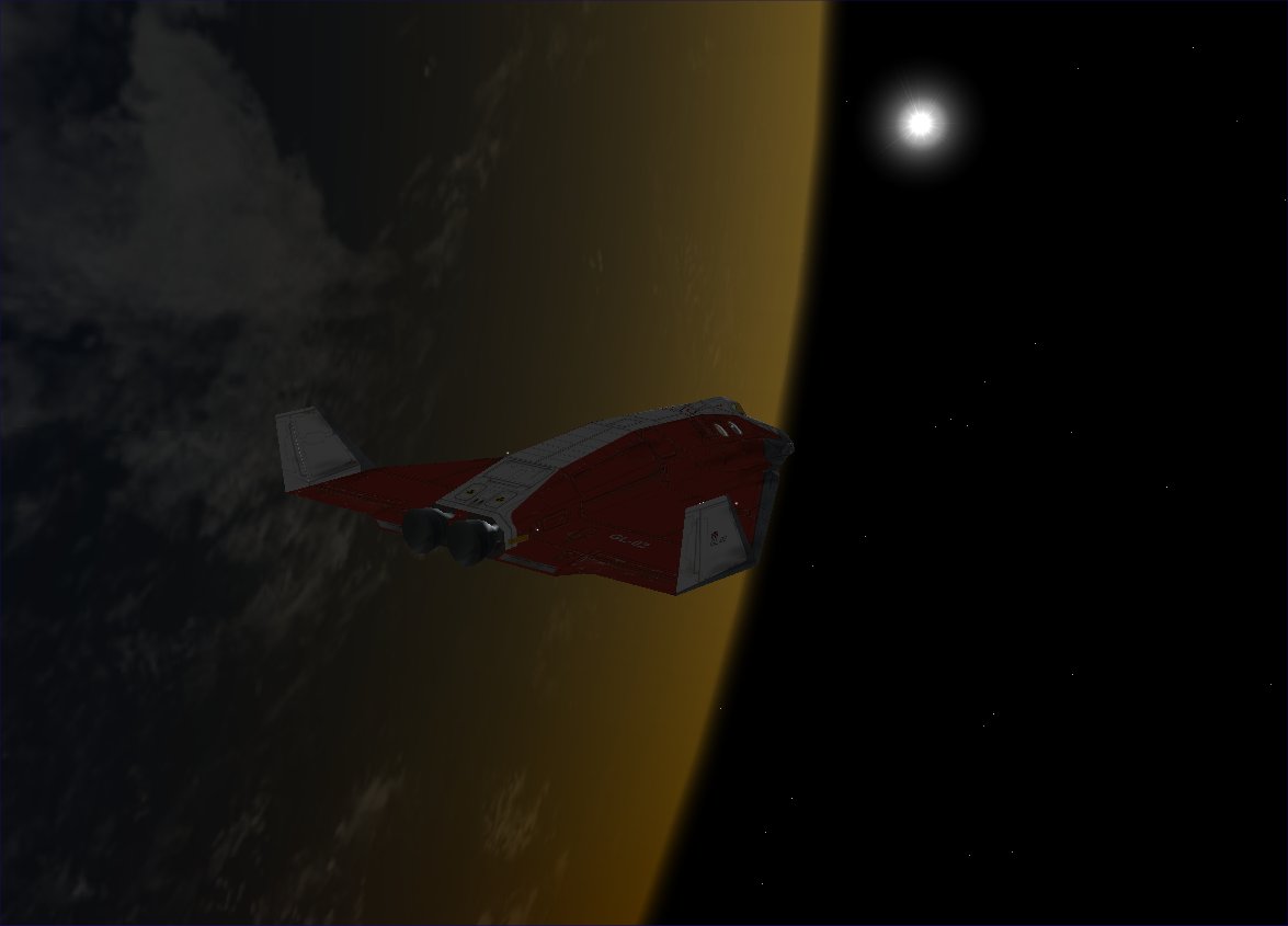
GPIS 2: Smack! Rescue
| Chapter 1: Before You Get Started | GPIS Contents | Chapter 3: Hovering At The Beach |
Acknowledgement[edit]
This material was contributed by Bruce Irving from the 2nd edition of Go Play In Space. Refer to the page's View History tab to see subsequent changes.
Smack! Rescue[edit]
The goal of this chapter is to get familiar with the basic operations and displays of Orbiter using mainly the mouse with on-screen controls and menu picks as much as possible (there may be a few keyboard operations). We start with a scenario that comes with Orbiter, building a little story around it, and explaining how to deal with the “emergency” this scenario presents. The idea that you would notice a critical orbit problem just minutes before you would need to take action is pretty unlikely, but unlikely situations are something that simulators are great for! For the story part, imagine that you are the pilot, and that the instructions and suggestions are coming from an instructor on the radio who can see all your flight data via telemetry. You can also start out by viewing an annotated playback of the mission instead of flying it yourself.
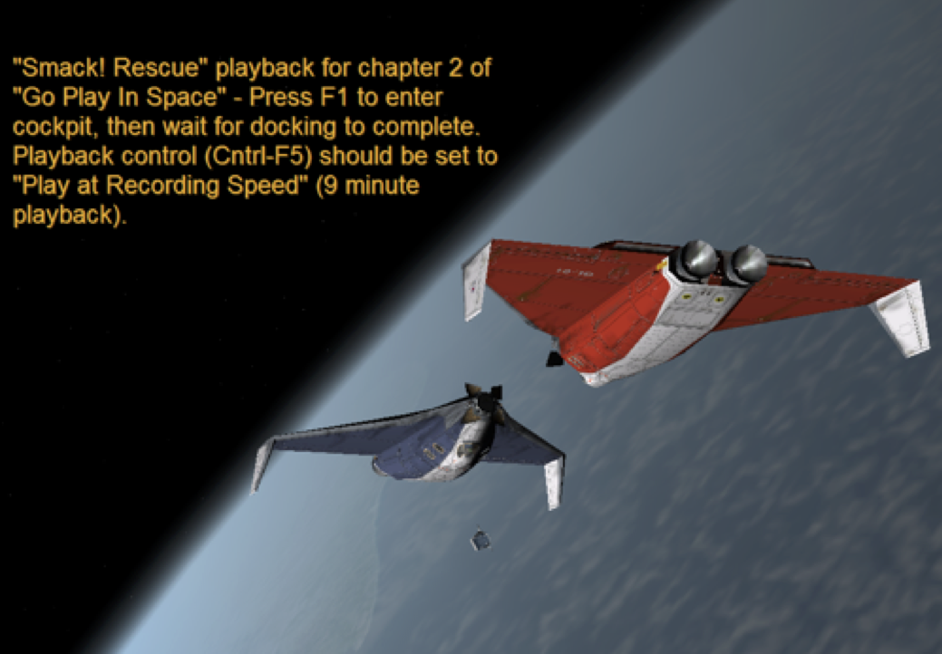
You’ve had some fun testing out the new “Delta Glider” (DG) rocket plane in low Earth orbit (LEO) the last few days. That’s a funny name for this spacecraft – with its powerful main and hover rocket engines, it’s hardly a glider, but whatever. Your tail number is GL-01, and you’re seconds away from docking with GL-02 flown by another pilot, Martin. It was Martin’s idea to add the synchronized rotation once the ships were lined up nose to nose – kinda cool. Not strictly regulation, and a bit dizzying, but it’s no big deal – you quickly learn in space that it’s mainly relative motion that matters anyway, and relative to GL-02, your ship isn’t really rotating.
| Two Ways To Start
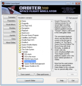
Thanks to Orbiter’s “flight recorder” feature, there are two ways to start out with this chapter. You can follow the instructions in the text, opening the standard supplied file “Smack!” and flying the mission exactly as described. Or you can open a different version of the scenario file that automatically runs a playback of the mission with on-screen comments telling you what is happening and what to do (you can still change views and MFD displays during playback). This playback is something like a movie or video except that it actually runs in Orbiter. Although the motion of the spacecraft is prerecorded, you can interrupt the playback at any time with vp and take over control yourself. To run the playback version, launch Orbiter and run the scenario Smack! Rescue found in the Tutorials scenario folder. |
Docking and Checking Status[edit]
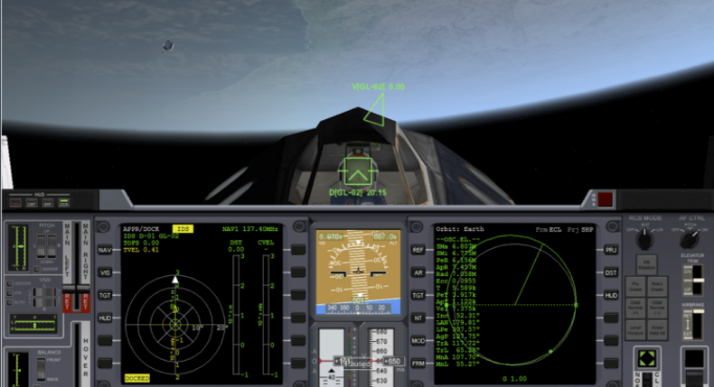
With a closing velocity (CVEL) of 0.69 meters/second on the Docking MFD, you’d be coming in a bit hot for space station docking (recommended CVEL of 0.1 m/s), but the DG docking ports are plenty strong. This is barely a slow walk (that’s about 1 meter/second), though these ships have a lot of mass, and you don’t want to bump the other ship too fast. The fact that both ships are traveling at a velocity (Vel) of 7389 m/s (7.389k in Orbiter format, 16,500 mph, 26,597 kph) relative to the Earth is important for a lot of things (like staying in orbit!), but it doesn’t affect much in the final seconds before docking.
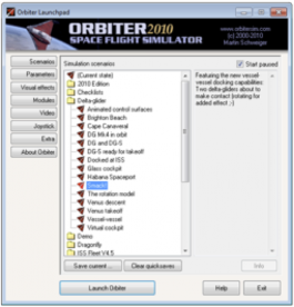
- Start Orbiter and launch the scenario Smack! that you’ll find in the supplied “Delta Glider” scenario folder. Review chapter one, “Before You Begin,” if you need any help doing this. This will put you in the cockpit of Delta Glider GL-01 with GL-02 quickly approaching and the Earth in the background appearing to rotate. You will need to follow and do all steps manually if you start with this scenario (left) rather than with the one in the Playback folder (right).
- You start out in the external view – hold down the RIGHT mouse button and move the mouse to pan the view, and use the mouse wheel to move the “virtual camera” in and out. Use PAGE UP and PAGE DOWN keys for camera control if you don’t have a wheel mouse – you can also pan the view from the keyboard by holding the Control key and using the arrow keys. NOTE: If nothing is rotating, you may have started in pause mode (as shown in the Launchpad dialog above) – press CTRL-P to toggle out of pause mode. You can press CTRL-P again any time you’d like to pause Orbiter.
- Press F1 if you want to switch to/from the cockpit view, but don’t touch any other controls yet. It’s all lined up so just wait a few seconds for the spacecraft to dock, for the docking sounds and confirmation, and for the message DOCKED to display in the lower left corner of the left multi-function display (MFDs are basically computer screens – the left and right MFDs can be changed to display many types of information, depending on what you need to do, but the Docking and Orbit MFDs are all you need for this chapter). NOTE: Other than with docking ports and with planet surfaces, Orbiter currently has no “collision detection.” If you miss the docking port, your spacecraft will pass through the other one without effect! Sorry, no explosions. If docking doesn’t automatically happen, start with the playback scenario and interrupt it with CTRL-P after it docks.
SMACK! That was a solid bump, but you’re safely docked. Time to review your status and prepare for some additional tests. First a quick look at the orbital elements on the Orbit MFD on the right – and right away something looks wrong. The orbital diagram shows that your periapsis is inside the circle representing the Earth’s radius - PeR is 6.156M meters, 6.156 Million meters, or 6156 km, and Earth’s radius is 6371 km. You do the math – the low point of this orbit is really low, about 200 km below the surface, and that’s not going to fly for long! Better double check with altitude mode on the Orbit MFD.
| Peri-WHAT?
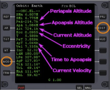
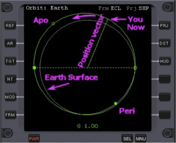
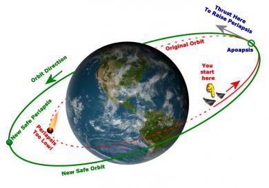
Orbits are usually ellipses (sort of egg shaped, an elongated circle). Periapsis is the lowest point in an orbit around any body (also called perigee in the case of an Earth orbit), apoapsis is the highest point (also called apogee for the Earth case). In the Orbit MFD diagram, periapsis is shown as a closed circle, apoapsis is an open circle. The “fixing up our orbit” graphics below should make this more clear, with labels added to show the key parts of the Orbit MFD and a picture of an orbit. There is also a section on understanding orbits in Chapter 10, “I Was Just Wondering.” This section explains the shapes of orbits and what the numbers that describe them mean. |
How could you have missed that? It must have happened as you changed orbits to rendezvous and dock. Altitude mode shows you are about 700 km above the surface now, but with a periapsis altitude (PeA) of -214.7k meters – below the surface. You need to raise that periapsis or you will be reentering the Earth’s atmosphere sooner than planned!
- Press F1 to go to the internal (cockpit) view if you are not there already. There are actually three cockpit views for the DG, the instrument panel view, a no-panel view, and a 3D “virtual cockpit” view (you can cycle these with the F8 key, but note that not all Orbiter spacecraft have panels or virtual cockpits). TIP: You can “raise your seat” (lower the panel) in the panel view with the UP-ARROW key (lower it with DOWN-ARROW). In our screen shots, we have put the lower edge of the MFDs at the bottom of the screen.
- Click the distance [DST] button on the right side of the Orbit MFD to switch to altitude mode. This on-screen button is circled in orange in the picture below. It changes the display from radius (Rad, distance from center of Earth) to altitude above the surface (Alt), and PeR becomes PeA with a value of –214.7k m (below the surface!).
- Click the mode [MOD] button on the Orbit MFD to cycle display modes. Also circled below, this lets you display the orbit diagram, the numbers (orbital elements), or both. In the figures below we have labeled the orbital parameters that are most useful in this scenario. Other orbital parameters are important too but are not directly needed in this situation. For example T is the orbital period, the amount of time needed for one complete revolution around the Earth. For this orbit, that period is 5.589k seconds or about 93 minutes, but that’s rather theoretical since if you don’t fix up this orbit soon, you won’t complete the next one anyway!
In the right hand diagram you can better see the dots for periapsis (Peri) and apoapsis (Apo) as well as the gray outline of the Earth’s surface and the green line (“Position vector”) which indicates your position. This is a typical “prograde” orbit so the position vector sweeps around counterclockwise as shown by the curved arrow at the top, in the same direction as the Earth’s rotation. We’ll discuss the square dots (called nodes) in a later chapter.
Fixing Up Your Orbit[edit]
The best way to raise the periapsis is to make a prograde main engine burn (accelerating in the direction we are orbiting) when you reach apoapsis as shown in the graphic above. When will that be? Check the labeled Orbit MFD shown above – ApT is time to apoapsis, and it’s 1064 seconds from now (1.064k, k meaning “thousands”) which is about 18 minutes, so you better get ready to make that burn! Here are the steps you’ll need to follow.
- Kill the rotation that still has the docked ships spinning relative to the Earth.
- Undock, use thrusters to separate by 30-40 m, and hold relative position (you might want to try to stay close together so you could re-dock quickly with GL-02 after both orbits are fixed, though you won’t actually dock in this chapter).
- Turn both ships in the prograde direction using the prograde autopilot button.
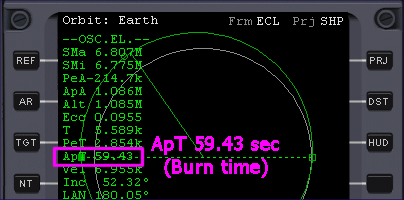
- Wait until “time to apoapsis” (ApT) is about 60 seconds and fire the main engines for both ships until eccentricity is as small as possible (maybe around 0.008 or smaller), which will raise the periapsis to a safe altitude and create a nearly circular orbit.
Kill Rotation and Undock – Start by killing your rotation and undocking. “Kill rotation” means to apply whatever rotational thrusters are necessary to cancel out rotations in all directions. It’s a very common operation, and though it can be done manually, the Kill Rotation autopilot is normally used. Since you are docked and the DG thrusters are pretty powerful, the autopilot in your ship will kill the rotation of both ships.
One small thing – there’s really no pilot in GL-02, so once you separate, you will have to pilot both ships! This is actually a cool feature of Orbiter – you can switch ships at any time (be sure the ship is in a stable situation before leaving it, especially if you plan to use time acceleration), and you can slow down or speed up time at will, which can really help you multitask.
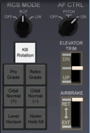
- Stop the rotation of the docked ships by clicking the [Kill Rotation] button on the right side of the control panel. Wait for rotation to stop (a few seconds).
- This can also be done with the KEYPAD-5 key (5 on the numeric keypad). This is one of several special purpose “autopilot” controls for doing common orbital tasks. Orbiter doesn’t have a standard general autopilot, but the special ones are usually enough. You can install add-ons from the web to automate many other tasks - even launching to orbit and landing on the Moon or Mars (see Chapter 9 on add-ons).
- Undock by pressing the CTRL-D command on the keyboard. You can do almost all actions in this chapter using the mouse to click controls and menus. Undocking has a screen button, but it’s on the lower 2D instrument panel which is reached with CTRL-DOWN-ARROW (use CTRL-UP-ARROW to go up a panel – the DG has an overhead panel too). Most operations in Orbiter are done with keyboard commands and most also have mouse/screen controls. Undocking gives you a small kick away from the target ship.
RCS Thruster Operations – You need to slowly back off from GL-02 then stop and hold position at about 30-40 m. So we will review thruster operations, concentrating on just three things for now, switching between rotation and translation modes, and the key commands for thrusting forward and backward.
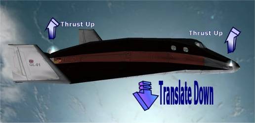
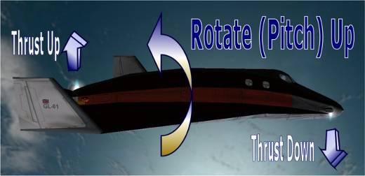
Thrusters are small rocket engines installed at several points on the spacecraft to be able to fire or “thrust” up, down, left, right, forward, and backward (picture above shows the right forward RCS cluster on the DG). They are also called attitude thrusters or reaction controls and are labeled RCS on the panel (RCS = reaction control system). By firing the RCS thrusters in various combinations, the spacecraft can be accurately rotated to point in any direction, or “translated” for small movements in any direction. You can rotate the ship up/down (pitch), sideways left/right (yaw), and right/left around the central axis of the ship (roll or bank). The directions for translation are up/down, left/right, and forward/backward.
RCS control is done with the numeric keypad on the right side of your keyboard. You’ll learn more operations in the next chapter but for this one, you only need three keys. The Orbiter manual (PDF file orbiter.pdf installed with Orbiter in its /Doc folder) also has some good diagrams and explanations (see section 15.2 “Attitude Thrusters”). The whole RCS and engine control keypad will be explained in the next chapter.
- Press the KEYPAD-/ key (not the main keyboard key) to switch from rotation to translation thruster mode. The keypad number keys control both rotation and translation, and the KEYPAD-/ key toggles between the two modes. The RCS mode is shown as a rotary switch at the upper right corner of the panel (it says OFF, ROT, or LIN – you can also change modes here with the mouse, but the keypad is better since you often have to switch modes repeatedly when docking etc.). With Orbiter Sound installed, you will also hear a voice say “Translation” or “Rotation” to confirm the mode when you change it.
- Press the KEYPAD-9 (thrust back) key a few times to get a CVEL of about –0.70 m/s or so on the Docking MFD. The Docking MFD will also show a green bar when you are moving away from the “target” and a yellow bar (or red, which means you are closing too fast!) when you are moving toward the target.
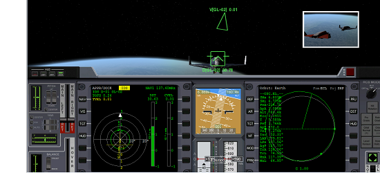
- When the Docking MFD shows a distance (DST) of about 30-40 m, press the KEYPAD-6 key (thrust forward) a few times to try to get CVEL to zero. A CVEL of -0.01 to +0.01 is OK but zero is the goal. If you overshoot, use 9 to thrust back a little again (see Tip below). Alternate between 6 and 9 as needed to zero it out. Now you are holding position at a fairly safe distance relative to GL-02 so you can both maneuver a bit. The Docking MFD below shows DST 30.63 m, CVEL 0.01, and TVEL (transverse or sideways velocity) of 0.01 m/s – so GL-02 is at 31 meters and drifting very slowly relative to GL-01. TIP: Holding down the CTRL key while pressing thruster keys applies “fine thrust” of 1/10th the normal value, ideal for making small corrections in your speed.
Note: This and later screen shots are taken with a wider FOV (field of view) than the earlier shot (now 50° vs. 30°, shown in upper right corner of screen) to show more of the outside world. Press the X key to zoom out (bigger FOV, wider view) or the Z key to zoom in (smaller FOV, more magnified, narrow view). Range is 10° to 90°. “Normal vision” range is roughly 40° to 60° depending on monitor size and other factors, but you should use what looks good to you.
Turn Prograde for the Burn – This is really just a single button click on the RCS panel, but for fun, you can slow down time so you can switch ships and get both GL-01 and GL-02 to start rotating into position at nearly the same time. There’s no real need for this, it just looks cool in the external view (and shows that you can operate multiple ships in a scenario). The [Pro Grade] button is another one of Orbiter’s special purpose autopilots. It automatically fires RCS thrusters as needed to point the ship’s nose in the “prograde” direction and to keep it pointed there if corrections are needed (prograde means pointing the nose in the direction of orbital motion – pointing tail-first is called retrograde and is also handled by a simple autopilot button).
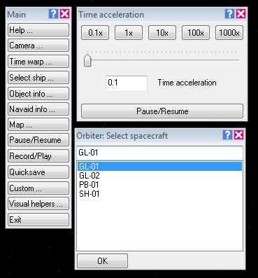
- Press F4 to open the main menu panel in the upper left corner of the screen.
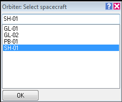
- Click the [Select Ship…] button. Move this small “Orbiter: Select Spacecraft” panel out of the way near the main menu panel in the upper left corner.
- Click the [Time Warp…] button. Move this “Time Acceleration” panel out of the way too.
- On the Time Acceleration panel, click the [0.1x] button. This slows everything in the simulation down to 1/10th of real time (i.e., 1 second of “Orbiter time” now takes 10 seconds of real time).
- On the ship’s panel, click the [Pro Grade] button. You can press the [ (left bracket) key instead. The ship will start turning to line up with the orbital direction, but in slow motion due to the 0.1x time setting.
- On the Select Spacecraft panel, quickly click GL-02 in the list, then click [OK]. You are now in the other ship! Move the mouse pointer off the ship panel.
- On the GL-02’s panel, click the [Pro Grade] button.
- On Select Spacecraft, click GL-01 and click OK.
- Press F1 to go to the external view, then click [1x] on the Time Acceleration panel to return to real time. Watch the two ships rotate in near synchronization to line up for the burn. Leave the panels for the main menu, select ship, and time acceleration open for later use.
| Mouse Note on “Input Focus”
The panels for the main menu (F4), time acceleration, ship selection, etc. can stay open while you do other things, which is very convenient for quick access (though it doesn’t help the outside view). By default they are activated (“input focus”) by a “mouse over” rather than with a mouse click, so be careful not to accidentally leave the mouse pointer over one of these panels when you try to type keyboard commands to Orbiter – Orbiter won’t “hear” you. |
Make the Apoapsis Burn – You need to wait a little while now to reach apoapsis. Once there, since you are using the prograde autopilot to stay pointed in the right direction (along the orbital “velocity vector” – basically the direction of our orbit), you can then just fire the main engines as you monitor the eccentricity (Ecc) of your orbit.
Look at the value of ApT in the Orbit MFD. This is the time in seconds until you reach the next apoapsis point (times are always in seconds, 600 s = 10 minutes, 3600 s = 1 hour, etc.). Look also at the eccentricity value (Ecc). This is what you hope to drive to zero to make your orbit circular.
- Carefully use time acceleration if desired to get close to apoapsis faster - click the [10x] button in the Time Acceleration panel. Watch the ApT carefully in the Orbit MFD and switch back to [1x] when ApT reaches about 100 s. You don’t want to miss the burn position in this situation.
- 'At ApT = 60 s, press the [0.1x] button in the Time Acceleration panel. This will slow things down so you can get the burn set up in both spacecraft.
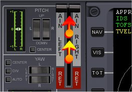
- Use the mouse to drag the main engine controls to the top (full thrust). The main engine throttle handles are on the left side of the panel. Be careful to position and drag the mouse between the handles – this will drag both throttles at the same time (if one engine’s thrust is higher, you won’t accelerate in the right direction). TIP: KEYPAD-+ gives full main engine thrust and the CTRL key will lock it in.
- In the Select Spacecraft panel, click on GL-02 and click OK to switch ships.
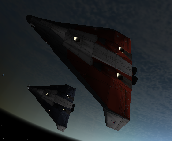
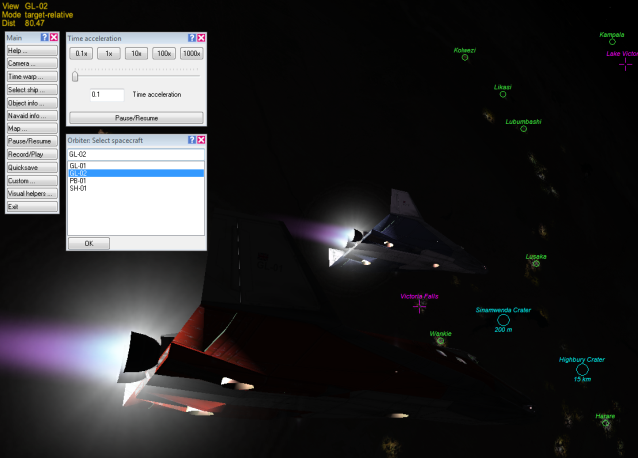
- In the GL-02 cockpit, quickly drag the main engine controls to full thrust, then switch back to GL-01 in Select Spacecraft. You should first confirm that you are still in prograde mode in GL-02 (it should be OK). While still in 0.1x time, you may want to switch to external view F1 and see both ships with their engines burning on the night side of the Earth (see picture below – the white patches in the background are city lights in southern Africa, surface labels are on – click Visual Helpers… on the main menu to see how to turn on surface and other labels).
- Click the [1x] button in Time Acceleration and watch the Ecc value carefully in the Orbit MFD. TIP: The keyboard commands for time acceleration are T to increase by a factor of 10 with each press (1x, 10x, 100x, 1000x, 10000x, 100000x) and R to decrease by a factor of 10 on each key press, down to 0.1x. High time compression (1000+) makes long flights (like Earth-Mars) possible, but use with care especially near planets – even simple autopilot features such as Prograde can cause trouble with 1000x or higher acceleration (e.g., uncontrolled spinning which causes the autopilot to use up all of your RCS fuel as it keeps firing thrusters to try to stop the spin!).
- When Ecc reaches around 0.01, click [0.1x] again to slow down time. With time at 1/10th, the Ecc value will drop slowly – just wait for it.
- When Ecc reaches about 0.008 or lower and stops dropping, cut the engines (drag down to the stop position). TIP: You can cut the main engines instantly by pressing the KEYPAD-* key.
- Switch to GL-02 and check the Ecc value – it should be smaller too, but won’t be identical to that of GL-01.
- Cut GL-02’s engines when Ecc stops dropping (very soon).
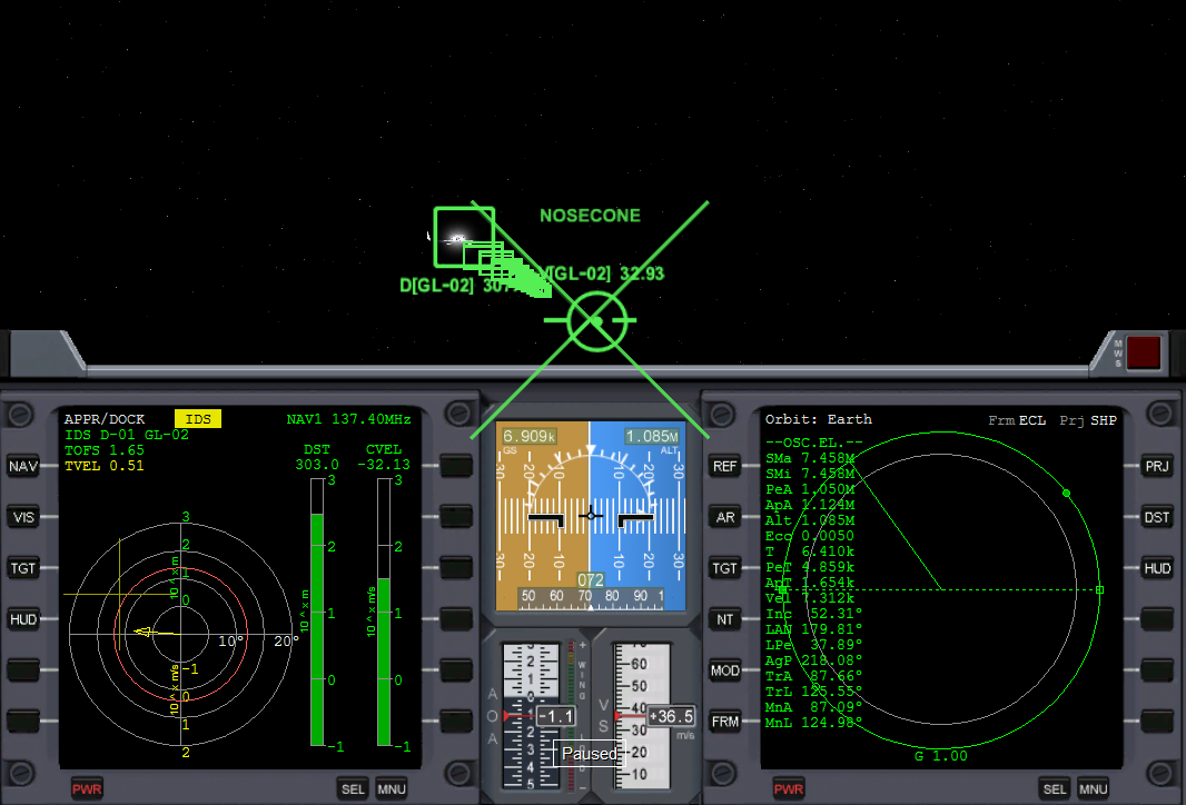
- Switch between ships one more time to confirm that engines are shut down, then return time to [1x] Congratulations, it looks like you saved the ship! The orbit looks safe (altitude 1059 by 1139 km, e = 0.0053 in our case, not quite circular which would be e=0). Your orbit will be somewhat different, and it’s not too critical here – as long as it’s well above 200 km and roughly circular, it’s OK in this case, though it certainly is possible and often necessary to reach more exact orbital parameters. The GL-02 should be pretty close at the moment, probably close enough to dock fairly quickly again if required. What are those green boxes? You never turned off the Docking MFD and Docking HUD (head up display) – the boxes are displayed by the Docking HUD as a “road in the sky” leading to the docking port of the designated docking target. GL-02 is facing the wrong way for docking right now, but you aren’t going to try that in this chapter anyway. There’s more about HUD modes in a later chapter. Time for a little sightseeing!
| What’s up with that nose cone?
The DG has a “flower petal” nose cone that opens for docking and is closed for atmospheric operations (flying in the air). Above 200 km the nose cone petals won’t cause any drag, so they could be left open, though it’s probably better (and looks cooler) to close them. You can find a handle for this on the lower control panel. Use CTRL-DOWN-ARROW to switch to that panel (there’s an upper panel too, that’s CTRL-UP-ARROW). Or you can just type K to toggle the nose cone doors. Both nose cones were closed in the flight recording. The big “X” is a warning that your HUD is in docking mode, but your docking port is closed (a mistake if you intend to dock). |
Quick Save the Scenario – This would be a good time to “quick save” the current situation for later use, and to either end the mission or to go do some sightseeing around the Solar System. Some users might have “quick saved” already in case of a mistake. This saves the current state of the simulation in a scenario (.scn) file in the Quicksave folder found in the Launchpad dialog. This allows you to later load and run that scenario to return to this exact time and space location instead of starting the scenario again from scratch. Orbiter scenario (.scn) files are very small text files so feel free to quick save often.
- If the main menu f4 is open, click the [Quicksave…] button, otherwise, you can press CTRL-S. A time stamped copy the current situation is saved.
- If you want to exit from Orbiter now, click [Exit] on the main menu, or press ALT-F4.
| When to Change What – An Important Orbit Rule
Under “Fixing Up Your Orbit,” we made the statement “the best way to raise the periapsis is to make a prograde main engine burn when you reach apoapsis.” This is true, but there’s a more general rule that’s worth learning. Remember that periapsis is the closest point, and apoapsis is the farthest point…
That might seem kind of backwards at first, but that’s how it works. Why? One key point to note is that any point at which you fire your engines must still be a point on your new orbit. So although your speed will change at this point, your ship won’t instantly “jump” to a new position, and any change in the height of the orbit must occur elsewhere. If your burn point is the periapsis, it will still be the periapsis after a prograde burn, and usually after a retrograde burn, though if you burn long enough retrograde, the apoapsis could get low enough to become the new periapsis, flipping the roles of the two points. Of course the speed and height of the orbit after a burn will change everywhere, not only at apoapsis or periapsis, and you could choose to fire your engines at any point in your orbit, and in any direction. The special thing about burning prograde or retrograde at periapsis or apoapsis is that the positions of these critical orbital points will not change, while burning at an arbitrary point or direction can change everything about the orbit. If the term “retro” sounds familiar, note that lowering your periapsis by the right amount and in the right place can set you up for reentry. Early spacecraft such as Mercury and Gemini had rocket packs dedicated to re-entry which were sometimes called “retro rockets.” |
Lua Script for Orbit Stabilization[edit]
Lua Script for Orbit Stabilization
This script is written using very basic Lua and Orbiter API calls. This is for two reasons:
- People just learning Lua are not exposed to some of the more advanced features of the language.
- I am just learning Lua, so I don't know much about these advanced features anyway
Notes:
- Configure Orbiter 2016 to display a Lua console window. This is accomplished by going to the "Modules" tab of the Launch Pad and checking "Lua Console" under "Script tools and drivers."
- Start the "Smack!" scenario. Using the scenario tab in the Launch Pad, go to "Delta Glider" and select "Smack!" by double clicking on it.
- Bring up the Lua console once the scenario starts with CTRL-F4.
- In the Lua console type "run ('Chapter2')." I used 'Chapter2' as the name of the script. If it is saved under a different name, use that name. The Lua script can be started at any time once the scenario has been initiated. It will wait for the vehicles to dock before continuing.
- Once upon a time, the script was written so that 10x time was used during vehicle separation. This has been disabled (commented out in the script) in order to better control separation distance.
- Movement to apoapsis is run at 100x time because a 1x time it takes a while (and some would get bored over this time period). This speed is maintained until about +/- 20 seconds before apoapsis. Time to apoapsis is displayed as an annotation.
- Main engines are fired at +/- 10 seconds before apoapsis to begin orbit stabilization. Orbit eccentricities for both vehicles are displayed as annotations.
- The script has finished when "End Script" is displayed in the Lua console window. This will occur 10 seconds after orbit stabilization has been achieved. Do not close the console window until "End Script" has been displayed.
Space Tourist Time[edit]
That wasn’t really too bad, was it? Now that you’re in a better orbit, it’s time to figure out where you are exactly and to get ready for a little sightseeing. The Earth is the obvious view, but thanks to Orbiter’s amazing camera system, ship jumping, and planetarium features, you can really view almost anything in the Solar System in just a few mouse clicks, and even have a good idea of what you’re looking at. Your current spacecraft won’t go there just because you move the camera (think of it as a view from a possibly distant space probe) – your craft has to fly to get to other places (or you can “cheat” by switching to a spacecraft that is already in some distant location, or by using the Scenario Editor). There are no “warp drives” in Orbiter – but it does make good use of good old basic (Newtonian) physics, supplemented by a lot of time acceleration (often referred to as “time warping”)!
So How’s That New Orbit? Check the Orbit MFD in each ship and see what the new orbit looks like. What are the new periapsis and apoapsis (PeA, ApA)? As long as periapsis is well above 200 km (2.000M), it should be stable for quite a while. How fast are you going (Vel)? What’s your period of rotation (T is in seconds – divide by 60 for minutes)? Press the [DST] button and check the distance from the center of the Earth (Rad instead of Alt, PeR instead of PeA, etc.). After that, unbuckle your seat belt, float over to a window, and stare at the Earth for a while like the real astronauts do.
Where Are We Now? (Changing MFDs) – So far you have done well with the two MFDs that were open when the scenario started, but there are a lot of other MFDs in the basic Orbiter, and many more available as “add-ons” created by Orbiter user-programmers and posted on the web. In later chapters you will learn about more of these, but for now, you can just bring up the Map MFD to see what your orbit is passing over.
MFDs are controlled with on-screen buttons, and within a specific MFD, most operations can also be done with key commands. MFD key commands are based on the Shift keys, but with a special twist. The left Shift key controls the left MFD, and the right Shift key controls the right MFD.
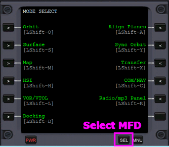
- Bring up the left MFD selection list by clicking the [SEL] button. This button is the only way to switch MFDs (no global keyboard shortcut to switch*).
- Select the Map MFD by clicking the button next to its name.
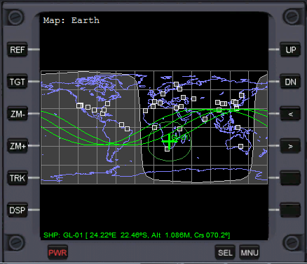
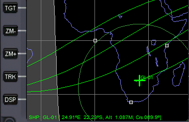
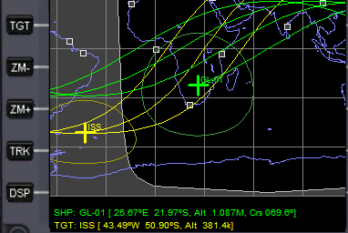
The Map MFD shows the track of your current and next few orbits over a map of the Earth. Where are you now? It looks like you are over Zimbabwe in Southeast Africa. Try out some of the MFD buttons, especially [ZM+] (below left) and [TRK]. You can also use the [TGT] button to select another orbiting object as your potential rendezvous “target” and display its orbit as well (your orbit is green, ISS target orbit is yellow, below right). Use the arrow keys and the Enter key on your keyboard to select a target from the list that pops up when you click [TGT] (the mouse doesn’t work on this list). The [MNU] button (next to [SEL] button) brings up brief descriptions for the buttons used by the current MFD.
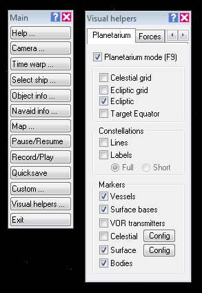
Visual Helpers (Planetarium) – If you want to know what you are orbiting over in more detail, or whether that bright dot is a planet, a star, or the International Space Station (ISS), take a look at Visual Helpers. This brings up a panel with check boxes to control the display of all sorts of labels.
- On the main menu, click on [Visual Helpers…] You can also press CTRL-F9 to bring up this panel. “Forces” allows display of lift, thrust, drag, etc. vectors on external views of spacecraft (labeled with dynamic force values).
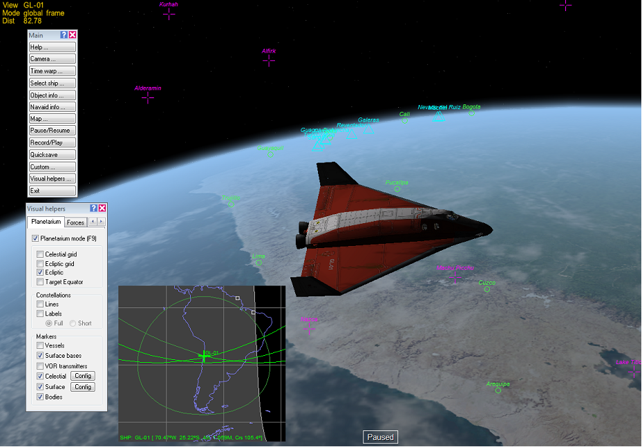
- Check the boxes for the items you want to see. Once you have selected the labels you want, you can close the panel or move it out of the way (though it’s pretty big). You can then turn labels on and off with the ª key alone. The labeled picture below shows the DG over the coast of Peru (map from Map MFD was added by hand in a graphics program).
- Visit Brighton Beach – This is a preview of some things from the next few chapters. Did you notice some other spacecraft listed in the Select Spacecraft panel? Some scenarios have spacecraft spread all over the Solar System, and you can jump to any of them with the Select Spacecraft (or F3) panel.
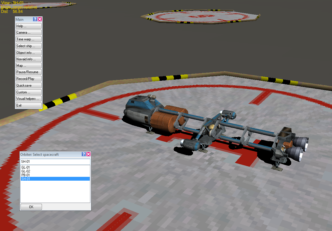
- In the Select Spacecraft panel, select SH-01 and click OK. SH-01 is a Shuttle-A, a rather bug-like spacecraft made for hauling freight in space (it doesn’t do too well in the Earth’s atmosphere – it has hover engines but no wings and not much streamlining – it can make it to Earth orbit if it’s lightly loaded).
- Use the right mouse button to pan around the SH-01. It’s parked on a pad at Brighton Beach. Isn’t that near New York City? Or is it in Sussex? Use your mouse wheel or PAGE UP key to pull the camera back as far as you like and see where this Brighton Beach actually is. You’ll be flying a DG there in the next chapter.
Visit the Planets – If you bring up one more main menu panel, you can take a quick tour of the Solar System courtesy of Orbiter’s camera controls. You can also view some spacecraft and space stations, but the available ones will depend on what is defined in the scenario file.
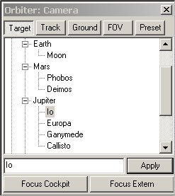
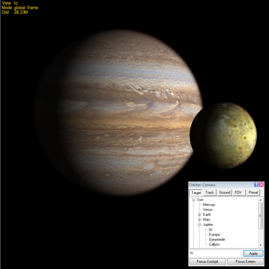
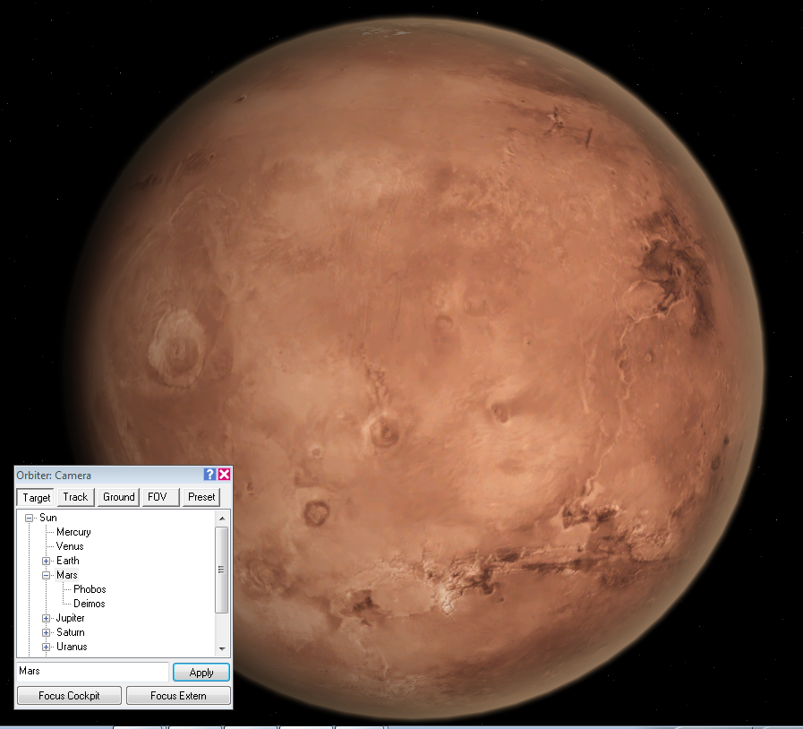
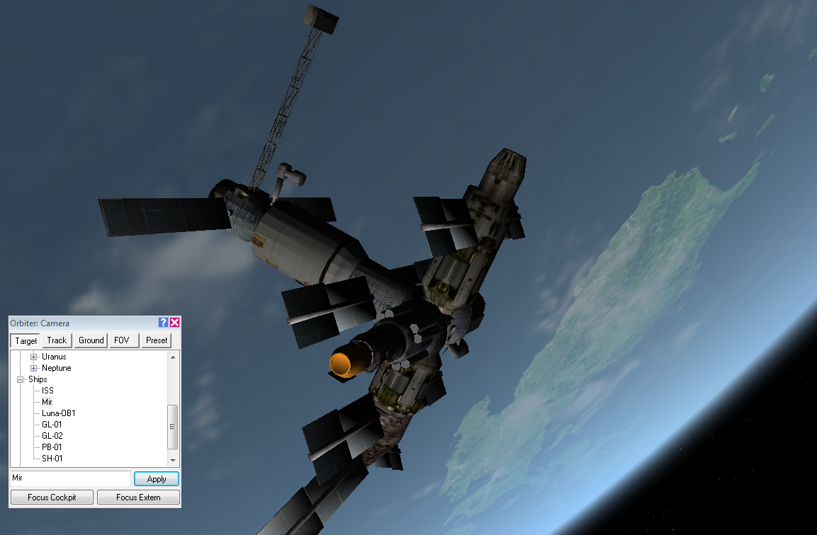
- On the main menu bar (F4 if it’s not open), click on [Camera…] This panel has several “pages” but the front page is what you need now. Click the plus sign labeled “Sun” to open the Solar System list, select a planet or spacecraft from the list (click the plus sign in front of a planet name to display a list of its moons if it has any), then click the [Apply] button. Your camera (but not your spacecraft) instantly jumps to a view of that planet or spacecraft (listed as Ships). Once displayed, you can use the normal viewing controls – right mouse button (or Alt-Arrows) to pan the view, the mouse wheel (or PageUp / PageDown keys) to change the camera distance. Depending on your previous camera and zoom settings, you may have to adjust something to see a new object that you jump to (you may be too close or too far).
- The other pages in the Camera panel are useful too. The [Track] button shows you the options for setting your camera position with respect to the target. The [Ground] button lets you set ground-based positions on some planets (especially Earth, good for watching launches and sunsets). The [FOV] page allows you to change the camera’s field of view (FOV) (you can also use the Z and X keys).
- Finally, some scenarios include pre-defined positions that provide useful or interesting points of view – access these (or define your own) through the [Preset] page.
- Here are a few examples of Orbiter views in the Solar System…
| Speeding Up the Planets
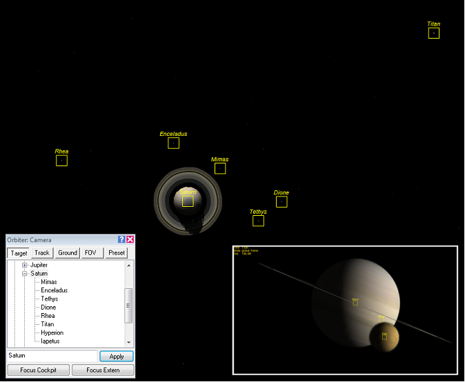
When you are out with your Orbiter virtual camera touring the Solar System, it’s really cool to speed up time and experiment with different views (mainly the F2 key, but Control-F1 gives more viewing options). First make sure you have all your spacecraft safely parked on something solid or in stable orbits with no autopilot buttons pressed (to avoid problems like uncontrollable spins and running out of thruster fuel when you’re not looking), unless you don’t care what happens to them – that’s OK, they bounce, and you can always start over with a new scenario. First look at the Earth from a few thousand kilometers out. Speed up time with T to 1,000x or even 10,000x and watch the Earth spin, watch the clouds move around, and watch the Sun set and rise every few seconds (slow down with R). Use the right mouse button to spin your view around. Depending on what the target is and what you hold fixed (F2 cycles between target relative, absolute direction, and global direction), you will see these features change in different ways. Experiment! The orbits of the multiple moons of Jupiter and Saturn are interesting to watch when speeded up (use planetarium mode, Control-F9, to turn on labels for “Bodies”). The effects of rotations and changing Sun angles on the appearance of Saturn’s rings can be pretty amazing. It’s also cool to put the camera on one of their moons (Io at Jupiter is always nice) and target the view towards or away from something else, like another moon, or Jupiter, or the Sun. It’s your Solar System, make it work for you. |
Summary of Steps (for Smack! Rescue)[edit]
Here is a summary of the main operations of this chapter (not including the “Space Tourist” section).
- Start Orbiter and launch the Delta Glider (DG) scenario called “Smack!”
- The two spacecraft are lined up and closing nose to nose, a few seconds from docking, which is automatic (hands off at this point). Switch between internal and external views as desired (F1 key) and rotate the view with the right mouse button.
- Go to the cockpit view (F1) – Orbit MFD shows current orbit is not stable (its low point or periapsis is too low and must be raised or you will reenter the atmosphere, click [DST] to view altitude, -214 km).
- Kill rotation (KEYPAD-5), undock (CTRL-D), switch to linear thrusters (KEYPAD-/), and thrust backward (KEYPAD-9) to a CVEL of around –0.70 m/s or slower.
- At a distance (DST) of 30-40 m, use forward thrust (KEYPAD-6) to zero out CVEL.
- Open the main menu panel (F4), then open [Time Warp…] and [Select Ship] panels.
- Click the [0.1x] button on the time acceleration panel to slow down time.
- Click the [Pro Grade] button on the right side of the main instrument panel to point the DG along its orbital direction.
- In the spacecraft selection panel, choose GL-02 and click OK to switch to it.
- Click the [Pro Grade] button in GL-02, then switch back to GL-01.
- Go to external view (F1), restore time to 1x, and watch the ships rotate to prograde.
- In the internal view (F1), watch the value of ApT (time to apoapsis) in the Orbit (right) MFD, carefully speeding time to 10x if desired. Go to 1x time when ApT reaches about 100 seconds.
- When ApT reaches about 60 seconds, slow time to 0.1x, and push main engine throttles (left main panel) to the top (full thrust).
- Switch to GL-02 on spacecraft selection panel, advance its engines to full thrust, and return to GL-01.
- Carefully watch the value of Ecc on the Orbit MFD as you return time to 1x.
- When Ecc reaches a value of about 0.01 or smaller, slow time to 0.1x again, and watch as Ecc continues to drop (very slowly at 1/10th time).
- When Ecc reaches a minimum value (0.008 or smaller), cut the main engines by dragging the throttles down to the stop point.
- Switch to GL-02 and check its Ecc value. If it is still slowly dropping, keep burning (at 0.1x time), cutting engines when it gets small enough (below 0.01).
- Switch back to GL-01, click time acceleration to 1x, and enjoy your new orbit!
| Chapter 1: Before You Get Started | GPIS Contents | Chapter 3: Hovering At The Beach |
Precis[edit]
This article has a precis and appears in the Random addon or Random article section on the Main Page. The precis can be found at GPIS 2: Smack! Rescue/precis and is displayed below.
|
Go Play In Space, Chapter 2. Go Play In Space is the classic introduction to Orbiter for new orbinauts and those looking to expand their horizons. Chapter 2 will teach you to maneuver your ship with a challenge to rescue another ship in trouble! (More...)
|
