ToddWessConstructionDiagrams
Drawings
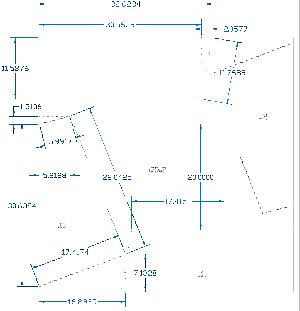
Figure 1
This figure shows dimensions and cutting pattern for parts L1, L2, R1, R2 and the base for C5, C6 & C7 to be cut from a piece of 48”x48” material. I used 1/8” plywood. When joining two pieces together, the joint was reinforced from below with ½”x1 ½” wood.
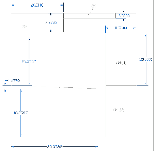
Figure 2
The figure below (diagram 2) shows the cutouts for panel C1 and C2 and the two pieces to make panel C3. I had to make C3 into two pieces so that I could fit all of the panels on 4 sheets of 48”x48” material.
The other two pieces are the support panels for panels L2 and R2.
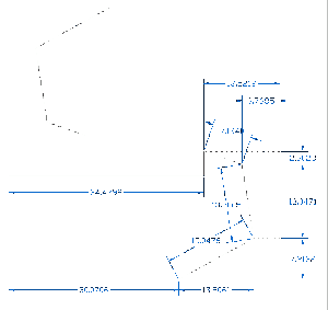
Figure 3
This figure shows the dimensions for cutting out the forward panel. Here it is shown in
two pieces so it can fit on the 48x48 piece of material. Once cut out, they were joined in
the back by three 3-foot pieces of wood.
One potential change to this is to divide the MIP into three pieces to make them more manageable, and join them using this template. The footwells are 24 inches wide, so the panel lines would be where the center console is.
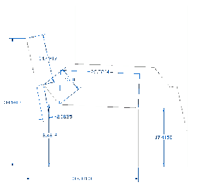
Figure 4
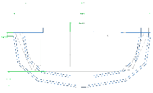
This figure shows the two side pieces that support the center panels. Panels C1, C2, C3 and the support board for C5, C6 &C7 go between these two. They also provide a notch and back-rest for the forward panels to sit on.
Figure 5
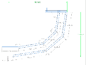 This figure shows the dimensions for the “cage” that I had originally built to be the front
of the cockpit. I never liked how this turned out, so I am no longer using it, but thought I
would include it here. I built it, then disassembled it.
This is dimension for half (obviously)
Figure 6
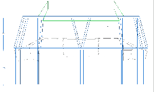
This figure shows the cage and the panels in an overhead view.
Figure 7
Here is a forward view showing the overhead panels attached and installed.
Panels O6, O7, and O8 were all placed on one large sheet that was 54” wide by 30” tall. Panels O5 and O9 were on either side, and were sort of tricky. I had to put the O6-8 physically in place and then fashion the panels in place. Here is a schematic of the panels. These panels are fairly straight forward, but O5 and O9 took a bit of trial and error.
Figure 8
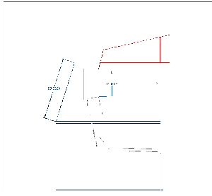
Here is a side view that helps show some of the angles between the panels. Again, the cage is shown in blue. You can see that panels O1, O2, O3 & O4 are at an angle to O6, O7 & O8, and that they protrude down a bit lower than the sides of panels O5 and O9. Also note that panels O6, O7 & O8 extend out further on the top past panels O5 and O9.
Pictures
Cage view 1 Picture 1
Cage view 2 Picture 2
Notes
Anything extra I can think of I will add here.
Using the default Atlantis and using the 3D cockpit helped a lot with special orientation while constructing this.
Some aspects of the cockpit are not outlined here. This document pretty much just covers the shell. For example, the additional forward panels (F1 – F4) were also constructed, but were fabricated on the spot and I don’t really have any documentation for them.
Also, the additional detail in the overhead panel was also done on the spot. I used pictures I download from the net to help design ad build this.
Lastly . . . windows I remember the simulators from Space Camp, and the windows were all blacked out. It gave a sort of “claustrophobic” feel that I liked. There was one simulator that was new, and still had windows in place from the factory that made it. It was very distracting to be practicing for a mission, and having a view of the cafeteria in front of you the whole time, next to a monitor showing the earth.
For this reason, I have opted for a closed window format. No windows have been cut out, and no windows have been depicted. Panels have been put in place where windows would have been and in the future, I may draw in window frames, but keep the windows blocked out.
