Difference between revisions of "Space Transportation System (STS)"
Soumya-8974 (talk | contribs) |
Soumya-8974 (talk | contribs) |
||
| (5 intermediate revisions by 2 users not shown) | |||
| Line 1: | Line 1: | ||
| − | The '''Space Transportation System (STS)''', also known as space shuttle, was developed by [[NASA]] as a | + | The '''Space Transportation System (STS)''', also known as space shuttle, was developed by [[NASA]] as a meant to move both crew and cargo into [[low earth orbit]]. |
| − | At launch the space shuttle | + | At launch the space shuttle was attached to an ET (external tank) and two SRB (solid rocket booster). |
| − | The SRB jettison at 126 seconds in-flight and fall back down to earth where they | + | The SRB jettison at 126 seconds in-flight and fall back down to earth where they would be picked up and refurbished for another launch. |
The ET will not be reused. | The ET will not be reused. | ||
| Line 9: | Line 9: | ||
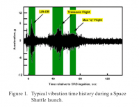
[[File:ShuttleVibrations.png|right|thumb|200px|Shuttle vibration amplitudes during ascent in g]] | [[File:ShuttleVibrations.png|right|thumb|200px|Shuttle vibration amplitudes during ascent in g]] | ||
| − | The STS Orbiter | + | The STS Orbiter was the primary component of the STS and the only part of the STS stack, which reached orbit. It was a mixture between spacecraft and aircraft, landing as a glider after a long lifting reentry. |
==Orbital Maneuvering System (OMS)== | ==Orbital Maneuvering System (OMS)== | ||
| Line 16: | Line 16: | ||
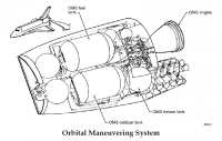
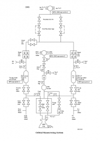
[[Image:OMS_diag.png|right|thumb|200px|Diagram of the OMS plumbing]] | [[Image:OMS_diag.png|right|thumb|200px|Diagram of the OMS plumbing]] | ||
| − | The OMS | + | The OMS would provide propulsion for the orbiter during the orbit phase of flight. The OMS wass used for orbit insertion, orbit circularization, orbit transfer, rendezvous, and deorbit. The OMS may be used to provide thrust above 70,000 feet altitude. Each OMS pod could provide more than 1,000 pounds of propellant to the RCS. Amounts available for interconnect depend on loading and number of OMS starts during the mission. |
| − | The OMS | + | The OMS was housed in two independent pods on each side of the orbiter’s aft fuselage. The pods, |
| − | which also | + | which also housed the aft reaction control system (RCS), are referred to as the OMS/RCS pods. |
| − | Each pod | + | Each pod contained one OMS engine and the hardware needed to pressurize, store, and |
| − | distribute the propellants to perform OMS engine burns. Normally, OMS maneuvers | + | distribute the propellants to perform OMS engine burns. Normally, OMS maneuvers were |
| − | done using both OMS engines together; however, a burn | + | done using both OMS engines together; however, a burn could be performed using only |
| − | one of the OMS engines. For velocity changes less than 6 fps (2 m/s), RCS | + | one of the OMS engines. For velocity changes less than 6 fps (2 m/s), RCS was used. For velocity |
| − | changes greater than 6 fps, a single OMS engine burn | + | changes greater than 6 fps, a single OMS engine burn was preferred, because engine lifetime |
| − | concerns make it desirable to minimize engine starts. Two OMS engines | + | concerns make it desirable to minimize engine starts. Two OMS engines were used for large |
| − | velocity changes, or for critical burns. Propellant from one pod | + | velocity changes, or for critical burns. Propellant from one pod could be fed to the |
| − | engine in the other pod through crossfeed lines that | + | engine in the other pod through crossfeed lines that connected the left and right OMS pods. |
| − | The OMS | + | The OMS had important interfaces with the data processing system and the electrical power |
| − | system. The OMS valves and gimbal actuators | + | system. The OMS valves and gimbal actuators received commands, and the system returned some |
data to the general purpose computers through multiplexer/demultiplexer units. Electrical | data to the general purpose computers through multiplexer/demultiplexer units. Electrical | ||
| − | power | + | power was supplied to the OMS through main buses, control buses, and alternating current |
buses for the operation of switches, valves, instrumentation, gimbal actuators, and heaters. | buses for the operation of switches, valves, instrumentation, gimbal actuators, and heaters. | ||
| − | The OMS/RCS pods | + | The OMS/RCS pods were designed to be reused for up to 100 missions with only minor repair, |
| − | refurbishment, and maintenance. The pods | + | refurbishment, and maintenance. The pods were removable to facilitate orbiter turnaround, |
if required. | if required. | ||
===Engines=== | ===Engines=== | ||
| − | The OMS engines | + | The OMS engines were designated left and right, descriptive of location. The engines were located in gimbal mounts that allow the engine to pivot left and right and up and down under the control of two electromechanical actuators. This gimbal system provided for vehicle steering during OMS burns by controlling the direction of the engine thrust in pitch and yaw (thrust vector control) in response to commands from the digital autopilot or from the manual controls. |
| − | The OMS engines | + | The OMS engines could be used singularly by directing the thrust vector through the orbiter center of gravity or together by directing the thrust vector of both engines parallel to the X axis. During a two-OMS-engine burn, the RCS would come into operation only if the attitude or |
| − | attitude rate limits are exceeded. However, during a one-OMS-engine burn, RCS roll control | + | attitude rate limits are exceeded. However, during a one-OMS-engine burn, RCS roll control was required. |
| − | Each of the two OMS engines | + | Each of the two OMS engines produced 6,000 pounds of thrust (26.7 kN). For a typical orbiter weight, both engines together would create an acceleration of approximately 2 ft/sec<sup>2</sup> or 0.06 g’s. Using up a fully loaded tank, the OMS could provide a total velocity change of approximately 1,000 ft/sec (304.8 m/s). Orbital insertion burns and deorbit burns each typically required a velocity change of about 100–500 ft/sec. The velocity change required for orbital adjustment is approximately 2 ft/sec (0.61 m/s) for each nautical mile of altitude change. Each OMS engines were capable of 1,000 starts and 15 hours of cumulative firing. The minimum duration of an OMS engine firing wass 2 seconds. |
| − | The OMS engines | + | The OMS engines used monomethyl hydrazine as the fuel and nitrogen tetroxide as the oxidizer. |
These propellants are hypergolic, which means that they ignite when they come in contact with | These propellants are hypergolic, which means that they ignite when they come in contact with | ||
| − | each other; therefore, no ignition device is needed. Both propellants | + | each other; therefore, no ignition device is needed. Both propellants remained liquid at the |
| − | temperatures normally experienced during a mission, however, electrical heaters | + | temperatures normally experienced during a mission, however, electrical heaters wre located |
throughout the OMS pods to prevent any freezing of propellants during long periods in | throughout the OMS pods to prevent any freezing of propellants during long periods in | ||
| − | orbit when the system | + | orbit when the system was not in use. |
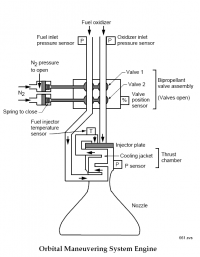
| − | Each OMS engine | + | Each OMS engine had a gaseous nitrogen tank that would provided pressurized nitrogen to operate the engine valves. The OMS engine would not have propellant pumps; propellant flow to the |
| − | engines | + | engines was maintained by pressurizing the propellant tanks with helium. |
| − | In the OMS engine, fuel | + | In the OMS engine, fuel was burned with oxidizer to produce thrust. The major elements of the |
| − | OMS engine | + | OMS engine were the bipropellant valve assembly, the injector plate, the thrust chamber, and the nozzle. |
| − | The [[Propellant|propellants]] ignite on contact, so theoretically the OMS engines could get ignited as often as desired, but the number of restarts | + | The [[Propellant|propellants]] ignite on contact, so theoretically the OMS engines could get ignited as often as desired, but the number of restarts were limited by the supply of N<sub>2</sub> used for operating the valves and purging the fuel lines of the engines, which was only enough for ten restarts. |
==Differences between the orbiters== | ==Differences between the orbiters== | ||
| Line 90: | Line 90: | ||
=STS addons for Orbiter= | =STS addons for Orbiter= | ||
| − | *[[Shuttle Fleet]], a collection of the whole vehicle fleet, by David413 | + | *[[Shuttle Fleet]], a collection of the whole vehicle fleet, by David413. |
| − | |||
| − | |||
| − | |||
| − | |||
=References= | =References= | ||
| Line 128: | Line 124: | ||
*[http://en.wikipedia.org/wiki/Space_Shuttle Wikipedia article about the STS] | *[http://en.wikipedia.org/wiki/Space_Shuttle Wikipedia article about the STS] | ||
| − | [[Category:Historic spacecraft | + | [[Category:Historic spacecraft]] |
[[Category:Launch vehicles|Space]] | [[Category:Launch vehicles|Space]] | ||
| − | [[Category: | + | [[Category:Manned space program]] |
| − | |||
| − | |||
Revision as of 08:46, 9 May 2021
The Space Transportation System (STS), also known as space shuttle, was developed by NASA as a meant to move both crew and cargo into low earth orbit. At launch the space shuttle was attached to an ET (external tank) and two SRB (solid rocket booster). The SRB jettison at 126 seconds in-flight and fall back down to earth where they would be picked up and refurbished for another launch. The ET will not be reused.
Orbiter
The STS Orbiter was the primary component of the STS and the only part of the STS stack, which reached orbit. It was a mixture between spacecraft and aircraft, landing as a glider after a long lifting reentry.
Orbital Maneuvering System (OMS)
The OMS would provide propulsion for the orbiter during the orbit phase of flight. The OMS wass used for orbit insertion, orbit circularization, orbit transfer, rendezvous, and deorbit. The OMS may be used to provide thrust above 70,000 feet altitude. Each OMS pod could provide more than 1,000 pounds of propellant to the RCS. Amounts available for interconnect depend on loading and number of OMS starts during the mission.
The OMS was housed in two independent pods on each side of the orbiter’s aft fuselage. The pods, which also housed the aft reaction control system (RCS), are referred to as the OMS/RCS pods. Each pod contained one OMS engine and the hardware needed to pressurize, store, and distribute the propellants to perform OMS engine burns. Normally, OMS maneuvers were done using both OMS engines together; however, a burn could be performed using only one of the OMS engines. For velocity changes less than 6 fps (2 m/s), RCS was used. For velocity changes greater than 6 fps, a single OMS engine burn was preferred, because engine lifetime concerns make it desirable to minimize engine starts. Two OMS engines were used for large velocity changes, or for critical burns. Propellant from one pod could be fed to the engine in the other pod through crossfeed lines that connected the left and right OMS pods. The OMS had important interfaces with the data processing system and the electrical power system. The OMS valves and gimbal actuators received commands, and the system returned some data to the general purpose computers through multiplexer/demultiplexer units. Electrical power was supplied to the OMS through main buses, control buses, and alternating current buses for the operation of switches, valves, instrumentation, gimbal actuators, and heaters.
The OMS/RCS pods were designed to be reused for up to 100 missions with only minor repair, refurbishment, and maintenance. The pods were removable to facilitate orbiter turnaround, if required.
Engines
The OMS engines were designated left and right, descriptive of location. The engines were located in gimbal mounts that allow the engine to pivot left and right and up and down under the control of two electromechanical actuators. This gimbal system provided for vehicle steering during OMS burns by controlling the direction of the engine thrust in pitch and yaw (thrust vector control) in response to commands from the digital autopilot or from the manual controls.
The OMS engines could be used singularly by directing the thrust vector through the orbiter center of gravity or together by directing the thrust vector of both engines parallel to the X axis. During a two-OMS-engine burn, the RCS would come into operation only if the attitude or attitude rate limits are exceeded. However, during a one-OMS-engine burn, RCS roll control was required.
Each of the two OMS engines produced 6,000 pounds of thrust (26.7 kN). For a typical orbiter weight, both engines together would create an acceleration of approximately 2 ft/sec2 or 0.06 g’s. Using up a fully loaded tank, the OMS could provide a total velocity change of approximately 1,000 ft/sec (304.8 m/s). Orbital insertion burns and deorbit burns each typically required a velocity change of about 100–500 ft/sec. The velocity change required for orbital adjustment is approximately 2 ft/sec (0.61 m/s) for each nautical mile of altitude change. Each OMS engines were capable of 1,000 starts and 15 hours of cumulative firing. The minimum duration of an OMS engine firing wass 2 seconds.
The OMS engines used monomethyl hydrazine as the fuel and nitrogen tetroxide as the oxidizer. These propellants are hypergolic, which means that they ignite when they come in contact with each other; therefore, no ignition device is needed. Both propellants remained liquid at the temperatures normally experienced during a mission, however, electrical heaters wre located throughout the OMS pods to prevent any freezing of propellants during long periods in orbit when the system was not in use.
Each OMS engine had a gaseous nitrogen tank that would provided pressurized nitrogen to operate the engine valves. The OMS engine would not have propellant pumps; propellant flow to the engines was maintained by pressurizing the propellant tanks with helium.
In the OMS engine, fuel was burned with oxidizer to produce thrust. The major elements of the OMS engine were the bipropellant valve assembly, the injector plate, the thrust chamber, and the nozzle.
The propellants ignite on contact, so theoretically the OMS engines could get ignited as often as desired, but the number of restarts were limited by the supply of N2 used for operating the valves and purging the fuel lines of the engines, which was only enough for ten restarts.
Differences between the orbiters
Columbia
Columbia (OV-102) was the first space-rated orbiter and was always the heaviest of the fleet. She was always the unique one with her SILTS(Shuttle Infrared Lee-side Temperature Sensing) pod on her vertical tail and the black wing chines. She was the only orbiter that never flew an ISS or Mir mission due to her mass.
However, her next mission following STS-107 was scheduled to be STS-118, going to ISS to deliver and install the S5 truss segment. Columbia was destroyed on reentry on STS-107, however, and STS-118 was later flown by Endeavour. Columbia was also capable of 16-day Extended Duration Orbiter(EDO) missions thanks the EDO cryokit in her payload bay.
Challenger
Challenger (OV-099) started out as Structural Test Article-099(STA-099) but when NASA decided against modifying Enterprise(OV-101) they decided to upgrade STA-099 into a spaceflight capable condition. During this refurbishment process she was known as OV-101M for a short while until she was later redesignated OV-099 keeping her STA number.
She was also a bit lighter than Columbia allowing her to perform IUS(Inertial Upper Stage) missions. Challenger had been modified at KSC to be able to support the Centaur G/G Prime upperstages, but she was destroyed during the launch of STS-51L prior to carrying any Centaur upperstages.
Discovery
Discovery (OV-103) was originally slated to become the "Air Force orbiter" stationed at Vandenberg AFB flying polar-orbit missions from Space Launch Complex-6(SLC-6, pronounced "slick six" ). However, the Challenger accident happened prior to the first Vandenberg AFB flight and the Air Force withdrew from the Shuttle program. She was then selected to fly the Return To Flight mission, STS-26R carrying TDRS-C.
Discovery also carried significant payloads such as the Ulysses Solar Polar Mission spacecraft and the Hubble Space Telescope. After Columbia, it looked for a while that Atlantis would fly STS-114, the Return To Flight mission. However, when engineers found problems with the actuators in the Rudder/Speedbrakes of the fleet, Discovery was selected once again to return the fleet to flight. She was retired in February 24, 2011.
Atlantis
Atlantis (OV-104) was pretty similar to Discovery, not much difference in mass or exterior appearance. Atlantis was used to launch Galileo to Jupiter and Magellan to Venus. Atlantis was the first orbiter to ever dock with Mir on STS-71 in July 1995. He was retired in July 8, 2011.
Atlantis is also the space shuttle that comes with the default Orbiter distribution.
Endeavour
Endeavour (OV-105) was built as replacement for Challenger utilizing spare parts NASA opted to build along with Discovery and Atlantis. Endeavour was the first orbiter delivered with an EDO capability and a 40 ft diameter drag chute used after touchdown to brake the orbiter on the runway. He was retired in May 16, 2011.
STS addons for Orbiter
- Shuttle Fleet, a collection of the whole vehicle fleet, by David413.
References
- Space Shuttle Operational Flight Rules - All Flights (5.3 MB PDF)
- STS orbiter subsystem manual
- Shuttle press kits from JSC
- shuttle press kits
- NASA Pocket Statistics: Payload & Equipment
GNC
- Real-Time Orbiter Abort Guidance, V. S. Sohoni, IBM
- Analysis of the Ascent Thrust Vector Control System, Independent Orbiter Assessment following STS-51L
- Unified Powered Flight Guidance Algorithm(C-4108), Space Shuttle G&N Equation Document No. 24 (Revision I), Brand, Brown, Higgins, Draper Laboratory, April 1974.
DPS
- DPS Dictionary - contains the descriptions and specifications of the CRT displays.
RSRM ballistic mass properties reports
These are the performance reports prepared by Thiokol, regarding the actual performance of the RSRM motors after each flight.
- RSRM-9 (360L009): Ballistics mass properties
- RSRM-11 (36OW011) ballistics mass properties (STS-35)
- RSRM-13 (360Q013) ballistics mass properties flight designation STS-41
For specific missions
STS-118
- STS-118 Reporter's Spaceflight Notepad (5.2 MB pdf)
STS-122
- STS-122 Reporter's Spaceflight Notepad (5.2 MB pdf) Summary for journalists by Boeing Communications, includes very well-done descriptions of the flight rules.
