Sirius-7K IDS
Command/Signal instrument (CSI)[edit]
CSI - a first type of an integrated control panel. It controls guidance systems and subsystems of spacecraft 7K-OK, signalizes executed commands, monitors the state of complex systems. In the IDS Sirius-7K are two CSIs: A left CSI and a right CSI.
Left CSI is installed on the port side of the ship, right CSI on the starboard. By design, both CSIs are symmetrical. However, one of them has control knobs (wafer switches), which have nothing to do with the matrix control loop. The control and monitoring from the CSI are carried out according to a matrix scheme: using the keys with text inscriptions, systems are selected, and the units are called for control, with the help of the number keys, commands are given to the unit of the selected system. The execution of commands is controlled by means of signaling devices, which are placed in the window parallel to the push-button switches.
The principle of matrix control is quite simple. However, its implementation at an object that changes its structure during the flight is associated with the need to organize the contours separately for the descent vehicle, instrument and aggregate compartments, as well as parallel and separate work of the commander and the ship's flight engineer. Control channels from KSU operate in the following modes:
- the left CSI is working, the right one is disabled,
- the right CSI is working, the left one is disabled,
- "both" mode - the left and right CSI work. In this case, the control of systems A, B, V, G can be carried out only from the left CSI, and the rest of the systems only from the right.
- both CSIs are off.
Modes of operation "left", "right", "both", "off" are set using the buttons, which are located on the dashboard.
Here are some of the technical characteristics of the CSI:
- weight …………………………………………………… no more than 3.35 kg,
- power consumption of one signaling device ………… no more than 0.3 W,
- power consumption during control …………………… no more than 1.6 W,
- the number of supplied matrix commands …………… 16 x 12 x 2,
- the number of monitored signal parameters ………… 16 x 16.
Command/Signal matrix (English translation)[edit]
| A | Б | B | Г | Д | Е | Ж | И | К | Л | М | Н | П | Р | С | Т | ||
|---|---|---|---|---|---|---|---|---|---|---|---|---|---|---|---|---|---|
| Backup Radio |
Radio D/L | Landing | ECLSS DM |
ECLSS OM, PM |
Airlock | Docking | Prepare Reentry Guidance |
Attitude Control System |
Navigation | Program | Propellant Supply System |
Back-up System |
RTS, RKO KM, SEP |
CEI | |||
| 1 | 2 | Prepare UHF XMTR I |
Modulation HF and UHF |
АСП | Light I | Guide from DM |
Prepare RDZ |
Select ДПО |
Cancel Mode |
Manual Control |
Cancel program |
RCS tanks |
Habitat Systems |
RTS, RKO | CEI | ||
| 3 | 4 | Prepare UHF XMTR II |
Back-up UHF antenna |
Air supply Valve |
Light II | Dryer | Supply interface |
Retract Probe (?) |
Select ДО |
DU | Orbit maneuver |
ДО nozzle | Propulsion System |
Back-up Antenna I |
Air composition | ||
| 5 | 6 | UHF RVR Simplex |
Dynamic OM |
XMTR mode Voice / Recorder |
Transfer light |
Reduce Press. in OM |
Manual docking | Indicator mode |
RO | βс | Approach "IE" | Supply ДО | Sealed Enclosure A / B |
Antenna II | |||
| 7 | 8 | UHF RCVR Duplex |
Microphone | Transmit | ?????? Light Ctrl. |
PO Valve | Egress Hatch open |
Lateral offset connection |
ИД разг.тор | Pulsed RO | γс | Automated deorbit |
Pressurize ДО |
PTD P gr |
Matrix I Off | Pitch/Yaw | |
| 9 | 10 | Prepare HF XMTR II |
Pyro-String I | Gas analysis | AC OM |
Basic press. open |
TV Camera A |
Pitch forward |
IO | αх | Deorbit by RO |
Supply ДПО |
Television | Matrix II Off | Peroxide ДПО | ||
| 11 | 12 | Prepare HF XMTR I |
Pyro-String II | Dehumidify | Inner Pump | Tank press. open |
TV Camera B |
Pitch backward |
Sun tracking |
СКД impulse |
Automatic Maneuver |
Pressurize ДПО |
Power СОУД | BKIP off | |||
| 13 | 14 | Frequency HF XMTR I |
Telegraph | Pyro-String ЗСП |
Dryer | Outer Pump I | TV Camera OM | TV scale Fluid/Manual |
Visor attitude |
Manual input |
Maneuver with RO |
Engine | Generator setting |
Solar battery off |
|||
| 15 | 16 | SW RCVR Duplex |
Narrow Frequency Modulation |
SA Fan | Outer Pump II | Televid. Filter (Dense - Light) |
Uncage gyros |
GB-A | Tube selection -Z, +Z |
Sun-oriented spin stab. |
|||||||
| 17 | 18 | SW RCVR Simplex |
Backup acoustics |
Light I | Movie Camera | Visor docking | Allow SKD ON from BUS(?) |
GB-B | "Star" | Telemetry | Peroxide SUS | ||||||
| 19 | 20 | Telephone ?? Transmitter |
Output Comm. |
Drain* I | Light II | OB (station?) Movie Camera |
Optical Index | Integrating Accelerometer |
BKIP | Engine Pressurization | |||||||
| 21 | 22 | Connect ?? Acoustic |
Inter-board Telephone |
Drain* II | Conditioning | Sun Sensor Light |
Suit Vent | Docking | Slip Manoeuvres |
||||||||
| 23 | 24 | ??? | VHF Beacon | Flow Valve Open |
Undocking | Thermal Sensors Off |
Uncage ?? | Emergency SKDU Pressurization |
|||||||||
| 25 | Frequency I | VHF Broadcast |
Separation | Flow Regulator Open |
Low Suit Pressure |
Docking mechanism ready |
Ion Flow | +Z Tube | PVU I Main | ||||||||
| 26 | Frequency II | HF Broadcast |
Atmosphere | Flow Regulator Closed |
Low Pack Pressure |
Contact | Pressurize SKDU |
-Z Tube | PVU II Main | ||||||||
| 27 | Frequency III | Dryer Shutter Open |
Dryer Shutter Open |
Mechanical capture |
|||||||||||||
| 28 | Frequency IV | Dryer Shutter Closed |
Dryer Shutter Closed |
Control from BO |
Divert | ||||||||||||
* Drain Valve? Gas/fuel dump?
Combined Electronic Indicator (CEI)[edit]
Program control indicator (ИКП)[edit]


The program indicator ИКП is designed for the control of the execution of programs, which are given by on-board Program Timing Unit (ПВУ), and permits the cosmonaut to determine:
- The name- and content-controlled program,
- Current time and program execution time for five programs,
- The time of some commands from the remote control,
- Execution command system objects,
- Health of the indicator ИКП.
The task of controlling the execution of the programs by the cosmonaut is to identify possible failures in the systems and the ПВУ and the timely issuance of control commands using the КСУ or special buttons on the control panel. ПВУ failure is failure to issue commands at a specified time. System failure is a failure of a system command, issued by the ПВУ.
A controlled program is a set of commands to be executed by system objects at a certain time and in sequence.
The sequence of commands in the programs and time of their execution are given by the ПВУ. Control of the execution on the indicator ИКП is carried out by a cosmonaut visually.
To do this on the control panel, electroluminescent indicators light up a time line with an index of time frame, the name of the program, the program contents in a list of commands to be performed, with each command bound for minute marks on the scale of the current time line and indices of the executed commands.
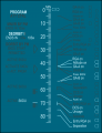
Types of information displayed on the ИКП are shown in Fig. 3.1 (mode control ИКП), 3.2 (program "Deorbit 1"). Other programs are shown in Fig. 3.3, 3.4, 3.5, 3.6, 3.7, 3.8, 3.9, 3.10.
A number of programs is running independently, and the program "Astro-Orientation" only with certain programs. In this case, it may be included in any time within 20 minutes relative to the moment of the beginning of jointly controlled program (before, after or simultaneously). Commands of this program are located in a certain sequence, but are not tied to the time line, for example, their execution time is not monitored.
The program is selected by radio command from Earth, or an astronaut by the КСУ. On the execution of any of the programs the time index starts to move along the scale of the current time line in intervals of 1 minute.
Upon reaching the time frame index-minute mark, which "connects" to any command, the command system will execute the appropriate index of the command. Response to a number of commands is indicated on the control panel by illuminating relevant inscriptions. If the indicator is not illuminated (or not extinguished), the cosmonaut must submit the appropriate command with the КСУ.
The device works in two modes:
- Standby control (ОК),
- Control by selected program (КВП).
While in standby control, it is only possible to do function self-testing of the instrument. On reception of the command "Self-test ИКП", every inscriptions, symbols, and indexes are displayed on the control panel. Simultaneously, the time index moves along the time line starting from zero time until the 85th minute mark. After reaching the last minute mark, the device returns to its original state.
The design of the instrument[edit]
Its basis is the structural frame, made of light alloy, of which one side is attached the control panel and on the other to polyurethane foam boards. On these boards are epoxy adhesive attached electrical components, which are also cushioned by the polyurethane foam board. The back cover of the device is made of polyurethane foam board.
The display panel consists of a frame made of light alloy, encasing the glass coated with a layer of electroluminescent phosphor. Glass is the first electrode. The second electrode has the configuration names, indexes, and symbols. Actually, these electrodes are a carrier of information, scheme ИКП - this scheme is controlled by certain sets of electrodes. The space between the electrodes is filled with epoxy resin.
Before the advent of liquid crystal indicators electroluminescent devices such as ИКП were unique not only for their information capabilities, small size, low weight and low power consumption. Thus, the ИКП in the "Sirius-7K" IDS together with the static converter, which is installed separately, consumed in the operating mode 400-600 mA and 420 mA in the self-test mode at a supply voltage of 27 V DC.
The way of displaying information conceived in the ИКП, opens new directions in building a man-machine interface. Here must be paid attention to two things:
- This is a time-programmed automatic control method to provide visual monitoring of program performance and participation rights in the implementation of the defined management programs aimed at achieving the set goals.
- Second, is the way the visual presentation of information in a specified sequential ordering of commands, not bound by time and other kinds of clues.
In essence formats like the ИКП replace astronauts instructions, in which they are forced to work with the absence of such indication. Thus, the ИКП can also be understood as an electronic trainer or support system for operators.
The author, being one of the leading developers of management systems simulator ТДК-7К for the cosmonaut training program "Soyuz-7K" in ЦПК Yuri Gagarin, indicates that the ИКП significantly simplifies the implementation of guidance procedures, and is a useful tool when you use the system in operation.
Introduction of time-programmed control method and controls at the panel is one of the greatest achievements of manned spaceflight. Its application in technical control systems for various purposes has a decisive influence on the organization of human activities in these systems. However for this method of control, though the effectiveness is confirmed by operating experience of the IDS "Sirius" inside simulators and in real flight, will not be widely used in the future.
One of the reasons - high complexity implementing changes introduced into the guidance program in the instrument panel.
When you use computer technology, this complexity is eliminated. Nevertheless, time-programmed display methods not received their development and for creating a fifth generation IDS - IDS ПКА "Soyuz-TMA" spacecraft, for example, more than 30 years after the introduction of IDS Sirius-7K. The main reason of this paradoxical phenomenon is a kind of peculiar to the Russian manned space flight, the attitude of the parent company in the field of manned space flight to the role of astronauts aboard a manned object and the inability of the system, for example in the face of institutes of the Academy of Sciences, to change this situation.
Thus, the ИКП - the first multi-mode device, which together with the КСУ, for the first time in the practice of creating ergonomic systems was implemented as time-programmed control method and process control. These principles, according to the author, based on the results of original research and studies of the Soviet scientist G.V. Koreneva, are fundamental to the future management systems.
Translations of the display modes[edit]
English: Deorbit 1

Digital Information Unit (БЦИ)[edit]
The БЦИ is:
- To control the process input settings in the gyroscope unit in automatic trajectory correction phase
- For manual entry of a gyroscope settings in manual trajectory correction phase.
- To control the amount of propellant resources in the vernier engine tanks.
- For signaling to the backup engine СКД
- To issue an command on remainder of the emergency propellant level in СКД <<150.0 m/s
The schematic drawing of the front БЦИ shown in Fig. 4.1 and a photography on Fig. 4.2.
This instrument consists of six decimal electromechanical registers operating by counting serial pulses with an electromagnetic drum-type stepper motor, and an electroluminescent light labeled "Reserve СКД".
Five registers, intended to control the input settings, have two stepper motors that allow pulse count in both the forward and reverse direction.
The sixth counter ("Resource СКД"), designed to control the propellant levels in the СКД tanks, only works as countdown. At the moment of automatic trajectory correction, the input register sets the celestial angles relative to azimuth and elevation of the Sun (βs and γs angles), the rotation angles in respect to body axes (αх and αу) and the velocity change target of the main corrective engine ("Impulse СКД") to the number of pulse-codes received.
Register settings in this mode are indicators by which the cosmonaut can judge the magnitude and direction of the impulse by the main corrective engine required for a given change in the trajectory of the ship.
At the manual correction phase, the astronaut enters the settings manually with the help of special racks. Input values are communicated from Earth. If you enter the registers, they work in reverse mode. Input is reset to zero, when the corresponding register receives a reset signal. Frequency of reading is 16.66 Hz.
The gear ratio of the stepper motor to the least significant digit drum counter is chosen such that the input of a single pulse modifies the counter at 0.044 m/s, which corresponds to the actual velocity increment by the engines during a time period equal to one pulse at a frequency of 16.66 Hz (Note: Corresponds to acceleration by СКД of 0.733 m/s²).
Upon reaching the counter value of 150.0 m/s a contact is triggered, giving the signal for emergency propellant level for the СКД. When operating the backup engine, the БЦИ lights up electroluminescent indicator "Reserve СКД" on the front panel.
Conclusions[edit]
БЦИ device, as well as КСУ, КЭИ, and ИКП are multi-functional devices which solve complex problems of guidance and control. This is direct control and management of the system. At the present time the challenges of data entry and control are met by other means, but the functions are almost the same. Functions are important for advanced systems and design - just for the story.
[edit]
The ИНК is for issuing the astronaut the following information:
- The current location of the ship - a point the earth's surface over which the ship is at the moment
- The intended place of landing for the spacecraft for inclusion in the time of braking by the propulsion system (ТДУ),
- The number of revolutions around the Earth, from the time of reaching orbit,
- The zones of line of sight for VHF and HF radio communications.
- The physical geography and landing sites
- The entry or exit out of the shadow of Earth
Fig.5.1 shows the appearance of the ИНК, where:
- Window with cross hairs for review and reference coordinates on the globe.
- Indicator for the longitude of the ship relative to the surface of the Earth.
- Mode switch the display: «МП» - the landing site, «З» - Earth, «Выкл» - Off.
- Register for orbital period of the spacecraft.
- Digit select switch for orbital period.
- Rotary switch for setting orbital period.
- Register of the number of revolutions around the Earth. Register range 0 ... 999.9 .
- Input or reset switch for the the number of revolutions on the register.
- Switch for setting the specified angular distance traveled after deorbit.
- Indicator of specified angular distance traveled after deorbit.
- Switch «Орбита» to rotate the globe around the orbital axis. Used for setting initial coordinates of the ship relative to the Earth's surface.
- Switch «Э» - set the rotation around the globe of Earth's daily rotation. Used for setting initial coordinates of the ship relative to Earth's surface.
- Switch «установ. СТ»/"Set Sun angle" - setting of the remaining time enter or exit the ship out of the shadow of the Earth.
- Indicator of time remaining until the entry into or exit from the shadow of the Earth by the spacecraft.
- Switch «тень-свет»/"Shadow/Light" - select time, which the ship spends in the shadow of the Earth (as a percentage of the period of the orbit).
- Indicator of spacecraft latitude relative to the surface of the Earth.
- Electroluminescent indicator «Место посадки»/"Landing site". Illuminated after switching switch 3 to «МП».
The display is an electro-mechanical device that reproduces the movement of the globe of Earth in two axes: the axis of the orbital motion of the vessel and the axis of rotation of Earth. The device has a rather complex kinematics, which interact by the following mathematical relations:
- Movement of the latitude scale φ:
- Movement of the longitude scale:


Where:
- i
- inclination of the orbital plane to the equatorial plane,
- T
- orbital period of the spacecraft,
- angular velocity of rotation of Earth, taking into account the precession of the orbit,
- t
- flight time since crossing the equator by the spacecraft,
- longitude of ascending node.


Movement around the axis of the orbital motion of the spacecraft and Earth's diurnal rotation is transmitted through the gearbox from two stepper motors, operating on impulses coming from the single flight time unit.
One turn of the globe around the axis of the daily rotation occurs in a time equal to the sidereal day, taking into account the precession of the orbit relative to Earth's axis caused by the asymmetry of the Earth's gravitational field.
Around the axis of the orbit, the globe rotates with a period equal to the spacecrafts period of revolution around the Earth.
Thus, the trajectory of the spacecraft relative to Earth's surface is obtained as a result of adding the above two motions.
The design of the display provides the possibility of correcting the period of orbital motion of the spacecraft in the range of ± 5 minutes in increments ± 0.01 minutes.
The location of the vessel is determined on the map globe under the central cross-hair sight or by rotating dial devices of latitude and longitude. These devices are associated with the mechanism of the orbital and diurnal rotation of the globe.
The landing site of the spacecraft is indicated by turning the globe with respect to orbital axis at an angle which is determined by the flight path of the vessel moment of the braking propulsion system (ТДУ) to the moment of landing, and the axis of the poles at an angle corresponding to the rotation of the Earth due to the daily rotation during the motion of an object on a ballistic descent trajectory.
Switching of the ИНК from location display mode to landing display mode and back is performed manually by an astronaut with the mode switch of the display.
The device has a mechanism for manual adjustment of the rotation period of the globe relative to the orbital axis at a deviation from the nominal settings. Before the start the calculated value of the orbital period is set. It is assumed that the orbit is circular.
Correction is carried out on the first orbit of flight after the refinement of ballistic flight parameters of the orbit relative to Earth provided by ground tracking stations. Before the correction of the globe is turned off, showing the specified coordinates.
Then ИНК is activated by an astronaut at a specified time - the estimated time over a point on Earth's surface with specified coordinates.
On the globe white circles are applied - the locations of ground tracking stations (НИП). In the first stages of development of the spaceflight coordinate display, the information belonging to the НИП was top secret, so the operation was carried out by applying stickers of the НИП locations to the globe directly at the space port. The operation required great accuracy, and it was performed as a rule by the highly skilled worker A. Voltov, employee of the manufacturer of the ИНК (Leningrad). Later, this operation was performed prior to shipment by panel customer specialists with lesser qualification.
Essential for the flight is to know the time before entry into the shadows, out of shade and while the spacecraft is in the shade. This importance stems from the fact that the primary operation of spacecraft rendezvous and docking should be carried out on the illuminated side. Indication of the above parameters as a percentage of the orbital period is provided through the mechanism of the «свет-тень»/"light/shadow" indicator, which consists of inner dark scale and an outer light ring, whose motion is synchronized with the movement of the globe around the orbital axis.
On the outer ring of light is a scale from 0 to 48% of the orbital period, marked every 2%. In the dark inner scale is a black and white scale from 0 to 50% of the orbital period, marked every 2%. The time remaining before the entry and exit from the shadow of Earth is displayed in the range 0 - 20 min.
Other features of the ИНК:
- The ИНК is operated by a generator of rectangular pulses of amplitude of 27 V (+7 V, -8 V) at a repetition frequency of 1 Hz and a duration of 100 ± 1 ms.
- Period of the daily rotation of the globe is 23 hours 35 minutes 52 seconds.
- Period of orbital motion can be set in the range of 86.85 minutes - 96.85 minutes in increments of ± 0,01 min.
- The angle of inclination of the orbital plane to the equatorial plane is 51°46'(later released ИНК had other inclinations of the orbit).
- The error of the drum register turns is no more than ± 0,1 turns.
- The map has the following color coding:
- water bodies (Blue),
- dry land of lowlands and highlands to 1000 m above sea level (Yellow),
- elevations from 1000 m to 3000 m above sea level (light brown),
- elevations above 3000 m (dark brown),
- red lines - borders of the USSR,
- purple lines - borders of the socialist countries,
- black lines - the U.S. border,
- Map scale is 1:100.000.000 (1 cm ≡ 1000 km)
- The coordinate grid on the globe is marked as follows:
- The latitude is shown every 10° and digitized up to 70° with a repetition every 30° of longitude,
- Meridians are shown every 15° and digitized to 20°N and 20°S through 15° and 60°N and 60°S through 30°,
- Parallel, corresponding to 20°N and marked every 1°,
- diameter of circles with the numbers of UHF radio stations - 4 mm, with black lettering by font number 3.
- Circles marking the cities of Moscow, Kiev, Alma-Ata, Novosibirsk and Khabarovsk, which may support by radio communication via HF.
- The scale on the spacecraft latitude indicator is marked every 2°, and the scale field, corresponding to the northern latitude, are colored blue, while the scale field, corresponding to the southern latitude is colored in yellow.
- Instrument error in determining the location of the spacecraft on the globe is less than 100 km.
- The error in determining the predicted "landing site" is not more than 150 km.
- The indicator error when turning from the "landing site" mode to "Location" mode is no more than 200 km.
Conclusions[edit]
In the view of not only the author of this work, but many astronauts and NGO specialists at RSC Energia, ЦКБМЭ г. Реутов, РГНИИЦПК Y.A. Gagarin, СОКБ ЛИИ and others, ИНК is a beautiful and very flight-critical display. Information provided on it and the problems are solved with its use, are of fundamental importance for the operation of astronauts in conditions of real space flight and to ensure their security.
Nevertheless, this device has a drawback: it is a scheme of flight in a circular orbit, and therefore can not be used when flying on non-circular. This shortcoming is particularly evident during a flight on the transfer orbit during rendezvous and docking. Consequently, the number of astronauts demanded the removal from the panel. However, before moving to an electronic IDS of the fifth generation on the Soyuz-TMA spacecraft, that could not be accepted, as during a loss of communication with Earth ИНК was the only means by which astronauts could solve the problem of landing in a given area.
The functions, which were solved with the help of ИНК, are of fundamental importance. These functions are almost fully transferred to the new generation of IDS and are classified as before, to the main parameters of the IDS.
Electroluminescent Signal Indicator[edit]
| Radiation in DM | Undocking | Low pressure in DM | Air composition |
| ССВП Mode | Back-up Parachute | Launcher Malfunction | Temperature sensor triggered |
| Back-up battery | Depressurization of СТР | ||
| Ballistic Descent | Low Voltage | Guidance on roll | Hatch OM-DM open |
| КСУ lock removed | Fasten seat belts | Input axis | Landing |
| Uplink | Transmitter ДРК on | Gyroscopes uncaged | |
| Radio session | ДПО nozzle | Attitude | |
| ССВП Mode | Capture | ||
| Bad port docked | ДО nozzle | СКДУ activated |
Acronyms[edit]
- АСП
- Automatic landing program
- БДУС
- Rate gyroscope assembly system
- БКИД
- Ion flow sensor control system
- БС
- Stabilization system (for ДКД back-up engine)
- ДКД
- Back-up engine
- ДО
- 10N attitude control vernier thrusters.
- ДПО
- 100N attitude control and maneuvering thrusters.
- ЗСП
- Reserve parachute
- ИД
- Ion flow sensor
- ИКВ
- Инфракрасный Вертикали, Infrared vertical sensor
- ИКП
- Program control indicator
- КСУ
- Command/Signal Unit
- КЛП
- Logic switching unit
- КПЛ
- Command receiver
- ПВУ
- Program timing device
- ПК
- Control panel
- СД
- Sun sensor
- СКД
- Main engine
- СОУД
- Attitude and motion control system
- ССВП
- Docking and internal transfer system
- СТР
- Active thermal control system
References[edit]
- Системы отображения информации типа "Сириус" космических аппаратов "Союз-7К","Союз-А8","Союз-М",станций "ДОС-17К"
- Анализ и синтез подсистем СОИ ПКА