GPIS 6: Reentry
| Chapter 5: Dancing In The Dark | GPIS Contents | Chapter 7: Mars Awaits |
Acknowledgement
This chapter was written for the 3rd edition by Mark Paton, to be inserted after chapter 5. Refer to the page's View History tab to see subsequent changes.
Reentry
You've been in orbit, made rendezvous with the ISS and landed on the moon, but how do you get home to the green hills of Earth? Spaceflight is inherently simple: from a given position and velocity, orbits are predictable essentially forever. But once you hit atmosphere, the interaction of your craft with the air becomes much more complicated. Maybe you’re ready for that challenge.
This chapter has three sections. The first two give some background on entry vehicles and reentry trajectories. The last section gives instructions for reentry and landing after undocking from the ISS. Some of the instructions are written for use with an add-on vehicle, DanSteph’s Delta-Glider IV, and the add-on Aerobrake MFD.
Entry vehicle design
Quick Reentry Concept Overview
A vehicle designed for successful reentry must meet three main requirements:
- Protection from heat of reentry
- Protection of crew from excess g-levels
- Lift and steering for pin-point landings
The solution: Keep the heat shield at an angle to the flow (angle of attack) to provide both thermal protection and flight control. Rotate the lift vector around the spacecraft to provide steering capability.
- The heat shield then acts as a wing for both capsules and shuttle types
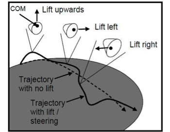
- The lift vector can be pointed upwards or sideways by rolling the spacecraft
- By managing the lift vector direction, the pilot can control altitude, distance and heading
Detailed information
Although winged vehicles and capsules look very different, they can be flown in the same way at hypersonic velocities in the atmosphere. This is because a capsule acts like a flying wing at high speeds. The hypersonic flow of air under the heat shield, when set at an angle to the flow, will push it upwards giving it lift. This angle is known as the angle of attack. Winged vehicles also fly at an angle to obtain lift this way. It is also a way to present the protective heat shield to the hot gases that form in front of the vehicle. The Space Shuttle flies at an angle of attack of 40 degrees to protect itself from the hot gases. The angle is so high that it presents a blunt surface to the flow, similar to what a capsule does. In this way the heat is carried away efficiently from the vehicle.
As the craft slows, the angle of attack for a winged vehicle can be lowered and its wings used efficiently. For capsules at lower speeds, the aerodynamic characteristics become useless and they have to deploy parachutes to control their landing speed.
At entry into the atmosphere, the amount of lift a vehicle produces in the vertical direction can be varied by rolling the spacecraft. The lift vector can then be directed upwards, downwards, left or right. If the lift is pointed entirely to the left this will generate zero lift in the vertical direction but maximum lift in the horizontal direction; it will turn to the left. In this way a vehicle entering the atmosphere can be steered safely with its heat shield still protecting it.
Winged vehicles have a higher lift capability than capsules due to their large wing areas. A measure of a vehicle’s lift can be expressed using the lift coefficient. Winged vehicles like the shuttle tend to have lift coefficients of around 1.0, while with capsules this is around 0.5. An important vehicle property is how quickly it is slowed down by atmospheric drag. This is normally larger than a capsule but not much larger. This property is expressed using the drag coefficient. Dividing the lift coefficient by the drag coefficient gives the lift over drag (L/D) which tells us something about the g-levels and how far the spacecraft can glide in the atmosphere. A high L/D will mean lower g-levels and large skips above the atmosphere. The ballistic coefficient is the mass divided by the effective area and tells us something about the distance the spacecraft can travel at altitude inside the atmosphere after the skip stage. A large ballistic coefficient (β) means that the spacecraft can travel a long way before being dragged downwards.
Table 1. Entry vehicle properties. Note the advanced properties of the Deltaglider IV: high L/D, low g-levels, and large β for long glides in the atmosphere
| Vehicle | AoA | Lift | Drag | L/D | Mass (mT) |
Area (m2) |
β (kg/m3) |
|---|---|---|---|---|---|---|---|
| Apollo CM | 60° | 0.43 | 1.20 | 0.36 | 6 | 10 | 500 |
| Deltaglider IV | 30° | 0.42 | 0.14 | 3.00 | 22 | 90 | 1746 |
| Space Shuttle | 40° | 1.00 | 0.90 | 1.10 | 100 | 250 | 444 |
Figure 1. Space Shuttle and Apollo Command Module oriented for atmospheric entry showing angle of attack.
Figure 2. Capsule flying
Trajectory Design
Quick concept overview
Trajectory requirements:
- Protection from extreme g-levels
- Management of peak heating and heat load
- A path to the spacecraft’s base
Solution: Lift is used to decelerate the spacecraft high in the atmosphere and to keep it there while it cools off. Large cross-range and heading errors during the early part of the trajectory can be corrected afterwards.
There are six distinct stages to the trajectory
- Deorbit burn at opposite side of the planet, reduce periapsis so orbit intersects atmosphere
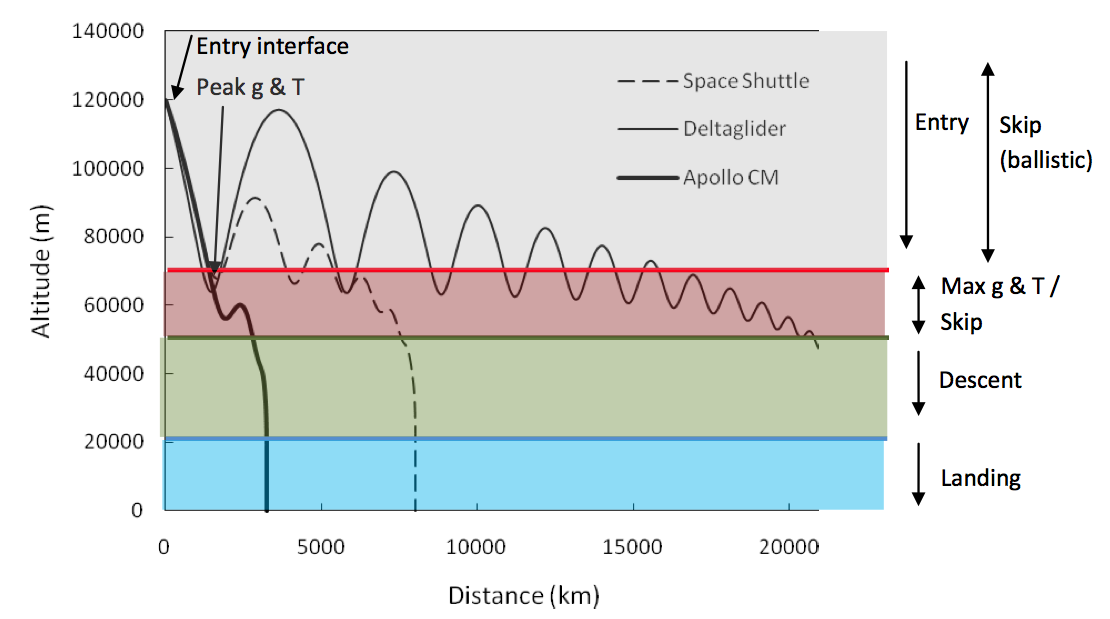
- Entry starts at 120 km down to about 65 km altitude. Small aerodynamic forces only.
- Peak g is when maximum g-levels and peak heating occur. Heading errors may occur here.
- Skip lift is used to maintain altitude or skip (allowing cooling) & to correct heading
- Descent Eventually lift cannot be maintained and drag dominates causing descent
- Landing At about 20 km spacecraft becomes subsonic. Flight using wings and parachutes.
Detailed Information
A spacecraft returning from space will need to remove its cosmic velocity so it can land without harming its crew or cargo. For this it uses the atmosphere to dissipate its kinetic energy. Due to the speed of entry into the atmosphere, air molecules are quickly compacted in front of the spacecraft. These impacted molecules obtain some of the spacecraft’s energy but are unable to move out of the way because of the neighboring molecules around them. The energetic molecules generate heat. If this heat is not managed properly it will build up in the surrounding gas and subject the spacecraft to extreme temperatures that could destroy it.
As the reentry continues, the atmosphere becomes thicker very quickly which will stress its structure and its occupants. These stresses are measured as the g-level. A g-level is equal to the acceleration due to gravity. A g-level of 10 would mean that you would weigh 10 times as much as normal, and that the wings would be trying to hold ten times the weight. If this is experienced for an extended amount of time it can cause damage. Both the g-levels and the heat transfer to the ship need to be managed carefully during the entry into the atmosphere.
Once an orbital path has been lined up to pass over the base there are six stages to reentry that have to be managed as outlined in the quick concept overview section previously. These are shown also in the figure below. Note how the space shuttle skips out of the atmosphere
Figure 3. Reentry profiles for three spacecraft returning from LEO. Apollo Command Module, Deltaglider and the Space Shuttle. The coloured lines mark the approximate altitude of the beginning of the last three stages.
The deorbit stage begins 180 degrees (i.e. about 18000-19000 km) from the base. The retro engines are fired to bring the periapsis down into the atmosphere, approximately over the target base. This causes the trajectory to intersect the atmosphere about 8000 km from the base at an altitude of 120 km. This location is known as the Entry Interface and is where the entry stage begins. The flight path angle at this point will be a couple of degrees below the horizontal. The entry angle is more or less fixed by the geometry of the orbit and there is little room for optimization of this parameter unless you are returning from interplanetary space. If the entry interface is too far from the base it can be moved closer by firing the retro engines past the 180 degrees point. Performing the burn about 15000 km from the base (approaching) will place the entry interface about 4000 km from the base.
What is important at this stage is to use the vehicle’s lift to manage the g-levels and heating once in the atmosphere. The peak g stage will occur once it hits the thick part of the atmosphere at around 65 km altitude. Around this time peak heating will also occur. Lift can be used to prevent the vehicle descending into the thicker reaches of the atmosphere. Care has to be taken to keep the vehicle in the atmosphere. If too much lift is generated then the vehicle will skip out of the atmosphere and can overshoot the base.
A comfortable g-level (and heating environment) is about 2g. For a space plane, it might be that only a fraction of the vehicle’s maximum lift capability is required. This is very convenient because then the remaining lift can be then be used to keep the vehicle high in the atmosphere during the skip stage so it can cool off. The lift can be used to launch the spacecraft out of the atmosphere on a suborbital hop or carefully vary the lift to keep it inside the atmosphere.
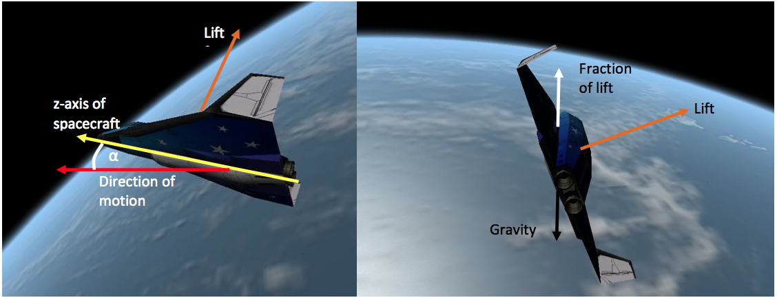
Skip trajectories are not used in reality because spacecraft have very limited ability to control their trajectory outside the atmosphere as their aerodynamic surfaces are unusable and their fuel is low during this time. The Apollo Command Module performed a shallow skip but remained in the confines of the atmosphere when returning from the Moon. The space shuttle performs low lift high drag maneuvers (S-turns) to keep itself inside the atmosphere. The vertical lift can be managed by rolling the lift vector around the spacecraft as shown in figure 4.
Figure 4. Rolling the lift vector of the Deltaglider IV. Here the bank angle is close to 90 degrees. This means most of the lift goes into steering the Deltaglider to the side.
One effect of varying the vertical lift during flight is to direct more lift into the horizontal direction. This causes the heading to change and moves the aerodynamic trajectory to one side of the ballistic trajectory (crossrange). This can be a drawback that needs to be countered by reversing the direction of turn; or it can be a benefit, allowing the vehicle to reach its target base even if the orbit doesn’t pass directly over it. During entry into the atmosphere the forces are greatest and most lift is directed into the horizontal. After the entry phase and maximum g it is necessary to correct the heading. This can be done by rolling the lift vector around to the opposite side of the spacecraft using the roll axis attitude thrusters.
It takes some time for the spacecraft to roll around. As the lift vector passes through the vertical axis (above or below the spacecraft) this will create large vertical velocities. To prevent a skip it is best to wait until the vertical velocity is a large negative value and then roll the lift vector over the top of the spacecraft. This will created large upwards accelerations during the roll and counteract the large downwards motion. Once the lift vector is on the opposite side the lift can be set to maintain constant altitude. When heading has been corrected the lift vector can be rolled again to the other side of the vehicle, taking care to manage the vertical motion of the spacecraft. This process can be repeated throughout the constant altitude phase to manage altitude and heading.
Eventually atmospheric drag will slow the vehicle down and the lift cannot be used to maintain altitude. The descent stage of the entry will then begin as the vehicle loses lift and descends into the thicker part of the atmosphere. At this point the heat shield will have cooled off and danger from overheating will have passed. The descent stage will begin at an altitude around 40 km and a velocity of around 2 km per second. The velocity will rapidly decrease making any large crossrange movements impossible. At about 20 km altitude the spacecraft will be approaching subsonic speeds and efficient use of wings is possible (or parachutes can be safely deployed); this is the landing stage.
Practice Scenarios
PROVIDE SCENARIO DOWNLOAD FILES
The first reentry practice scenario uses the Shuttle PB, which turns out to be a simple vessel to learn the basics of reentry. It is essentially a capsule, but its engine allows for adjustments greater than a pure capsule would achieve.
A couple of reentry lessons using the Deltaglider IV follow. Both use the scenario included with the Deltaglider IV package called “Docked to ISS”. You should download and install the Deltaglider IV, and the Aerobrake MFD. Instructions for finding and installing Orbiter add-ons can be found in the Chapter 9, A Bit About Add-ons. The Aerobrake MFD manual has even more detailed information about the interaction of spacecraft and atmospheres.
The first Deltaglider IV scenario is fairly easy. Once the orbital adjustments have been made and the angle of attack programmed into the flight computer, little or no atmospheric flying is required until the landing stage.
The second Deltaglider IV scenario is a bit more difficult. It makes use of the advanced aerodynamic capabilities of the Deltaglider, namely its high lift to swerve over North America and land at Habana. Some flying skills are required as from time to time the bank angle will need adjusting, although this will be fairly minimal.
This is a technique using Orbiter’s PB shuttle to make a precise landing at Cape Canaveral. This vehicle was chosen for the tutorial over the Deltaglider or other add-on vehicles for a number of reasons. Firstly the PB shuttle is native to Orbiter and so less complicated to get started for those new to Orbiter. Secondly the aerodynamics of space planes in Orbiter have excessive lift that make a straight forward reentry tricky to perform because they perform multiple skips out of the atmosphere during a belly down reentry. There is a technique using S-bends where the skips can be avoided by redirecting the lift forces sideways but this is requires practice to get right. Another issue is controlling the angle of attack during reentry which is difficult with space planes without and autopilot.
Using the PB shuttle with its modest lift capability allows a straight forward reentry without an autopilot. A precise landing is possible by using natural forces to control the angle of attack together with small adjustments using the Rocket Control System (RCS) during the reentry to control the cross range errors and short bursts of the main engine to reduce any down range errors.
1. Getting to know your vehicle
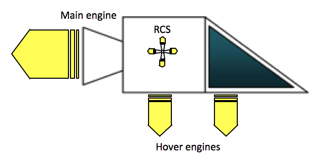
For this reentry tutorial we will use Orbiter’s native spacecraft the PB Shuttle. This is a small agile one seat craft that can be flown in space and in the atmosphere. It weighs 1250 kg fully fueled and 500 kg empty. It has a large main engine and two hover engines but lacks a retro engine so hover landings can be tricky and we recommend runway landings. For orientation in space the PB shuttle features a Rocket Control System (RCS) like many other Orbiter spacecraft. These are small engines that can rotate the spacecraft to a desired attitude and are useful for example, positioning the shuttle for a retrograde deorbit burn. Below is a schematic of the PB shuttle and its engines.
Figure 1. PB shuttle and its engines. Note in the Orbiter model there is no visible representation of the hover engine nozzles although there are exhaust flames. For the RCS there is neither visible representation of the nozzles or flames but the forces are modelled so they do have effect when operated using the numpad keys.
The PB shuttle is capable of landing from orbit simply by using its main engine to cancel out the orbital velocity and then descend into the atmosphere using its hover engines. However we are interested in conserving our fuel and practicing concepts and techniques that may be useful for aerodynamically controlled reentries that may be applied to less capable but more realistic spacecraft that are available in Orbiter.
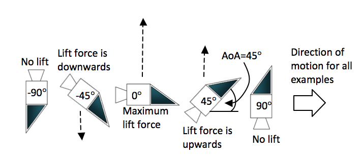
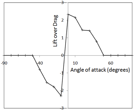
The reason the PB shuttle has been chosen for this tutorial is because it has a modest aerodynamic lift capability allowing a relatively quick descent compared to say more immersive spacecraft such as the Deltaglider. Aerodynamic lift is a force generated when the PB shuttle enters the atmosphere. The underbelly of the shuttle deflects the oncoming flow of gases and the air molecules transfer some of their momentum to your vehicle generating an upwards force (if the PB shuttle is orientated as shown in figure 2 at an angle greater than 0 degrees and less than 90 degrees). Understanding the effect of the PB shuttle orientation on the entry trajectory is key to controlling where you land so study the figure carefully.
Figure 2. Lift force divided by drag force for a range of angle of attacks. The angle of attack (AoA) is the angle that the underbelly of the shuttle has with the direction of motion. The Lift over Drag is the lift force divided by the drag force. Pointy objects like space planes tend to have high drag while blunt objects (like capsules) tend to have high drag.
2. Landing at Cape Canaveral tutorial
The following instructions will provide you with the necessary information to make a precise landing at Cape Canaveral. The method can also be used to make landings at other locations and bases on the Earth.
1. Undock from the space station (CTRL-D)
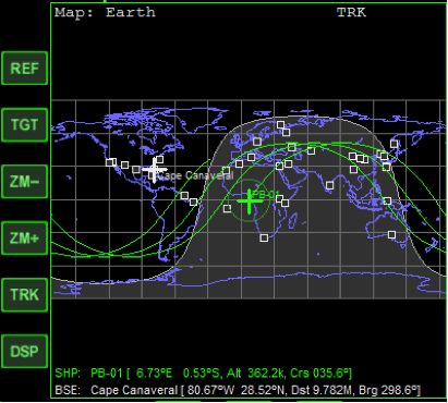
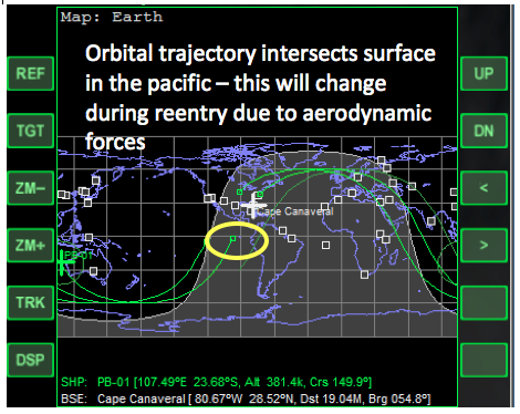
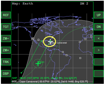
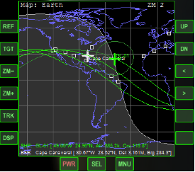
2. Select Cape Canaveral as the target on Map MFD by pressing TGT and then typing in “Cape Canaveral” into the dialogue box. The MFD screen will then look like the one shown below.
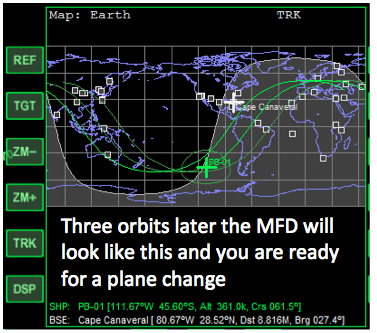
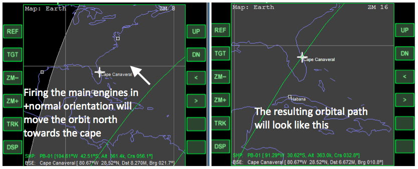
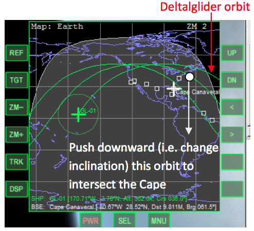
3. First you need to change your orbital plane so your orbital path will pass over Cape Canaveral. Wait until 3 orbits have passed. You can use time acceleration. Then there should be a trajectory drawn on Map MFD just south of Cape Canaveral. This we need to position over the cape. Use the normal + autopilot to orientate yourself with the nose pointing north out of the orbital plane. Apply the main engines to position this trajectory over the cape. Expect to use between 40 kg and 60 kg of propellant (i.e. about 700 kg left after the plane change burn).
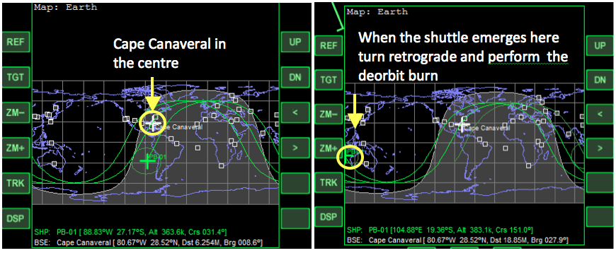
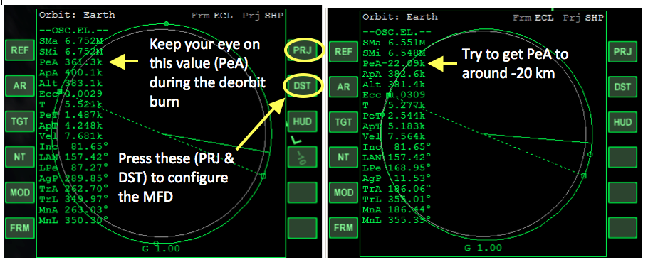
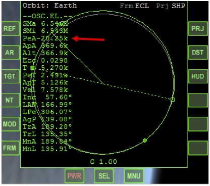
4. Now you need to prepare for the deorbit burn. First zoom out then use the arrow buttons on Map MFD to position Cape Canaveral is the centre of the screen (i.e. so there are six grid squares between the cape and the edge of the MFD screen). When you ship emerges from the left of the MFD screen use the retrograde autopilot to turn your engine facing the direction of motion. Then select Orbit MFD, change the projection so the orbit is shown as a circle. Also change the periapsis to “distance above the surface”. Fire the main engines for about 10 seconds until the periapsis distance is about -20 km. Map MFD should show your trajectory ending somewhere in the south Pacific ocean. We can modify the trajectory during entry so we land at the cape using the lift capability of the shuttle with some fine tunings using its thrusters.
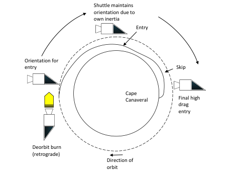
Figure 3. Orbital burn location and resulting entry path
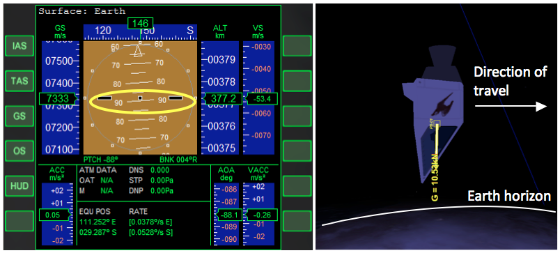
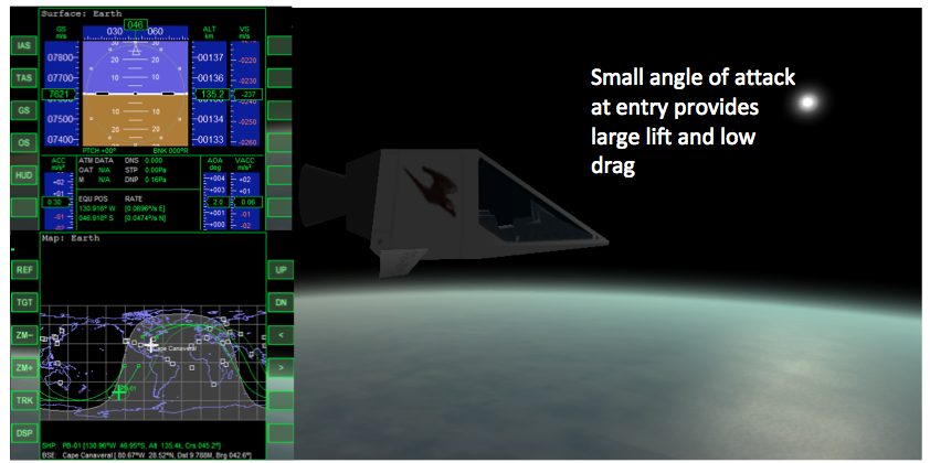
5. Next you need to prepare for reentry. Use prograde autopilot to point your nose in the direction of motion then use the hold level autopilot to level. Use yaw thrusters to line up the flight path indicator with the nose of the ship. If the ship does not respond you may have the RCS set to linear thrusters. Press “rot” on the HUD button to rectify this. Once everything is lined up use the “pitch down” thruster to rotate the nose downwards towards the surface of the Earth. When the nose is pointing ninety degrees to the direction of motion use kill rotation to stop the motion. As the ship rotates around the planet the nose will automatically be raised so the nose is pointing forward at reentry window and the correct angle of attack is used during reentry. From now on you will not need to control the orientation of the shuttle.
Figure 4. Entry trajectory and its shape related to changing orientation (lift) of the shuttle
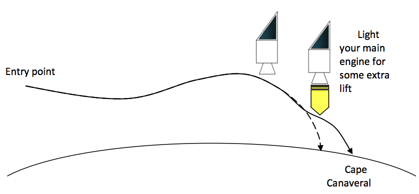
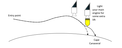
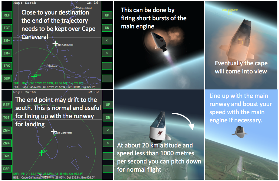
6. At about 85 km altitude your trajectory on Map MFD will start moving closer towards Cape Canaveral as the PB shuttle lifting surface have effect and cause the trajectory to skip out of the atmosphere. The end point of the trajectory needs to be located slightly passed Cape Canaveral. This can be done, if the aerodynamics has not done the trick, by firing the main engines for a few short bursts after the shuttle climbs out of the atmosphere (above 85 km altitude). The trajectory will then look something like that shown on Map MFD below.
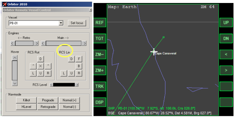
7. The trajectory may be slightly east or west of the cape. Use linear thrusters (recommend using Remote Vessel Control) to fine tune the position of the trajectory so it passes slightly west of the cape. Use left thruster (L) to move trajectory upwards. Using 10x time acceleration can speed things up. Use the Map MFD zoom function to get it as precise as possible.
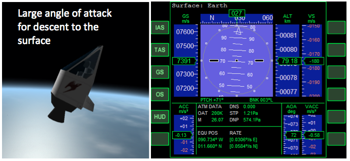
8. The shuttle will continue pitching up and reach about 70 degree at a maximum altitude of between 100 and 120 km. On the descending leg of the atmosphere skip, at about 85 km, the shuttle will be pitched at somewhere between 70 and 90 degrees with its nose pointing upwards. This will cause a non-lifting entry so the shuttle can descend to the surface without skipping out of the atmosphere.
9. As you fly lower into the atmosphere the denser air will reduce your velocity. As you lose energy the end point of your trajectory will become shorter and your intersection point with the surface will move further out to sea. To maintain your trajectory end point over Cape Canaveral use the main engines to provide a small boosts as you move close to the cape. Also keep an eye on your pitch. After reaching 90 degrees pitch the ship needs to be maintained at approximately at this angle so the main engine is pointing downwards. Don’t worry if the trajectory drifts to the south a bit, this is normal. Just keep the end point lined up at the same longitude as Cape Canaveral if this happens.
Figure 4 Modifying the trajectory during entry using the main engines.
- 1. Undock from the space station (CTRL-D)
- 2. Close the nose door (switch on top panel, CTRL-UP ARROW)
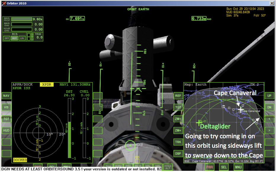
- 3. Select Cape Canaveral on Map MFD, press TGT and type in “Cape Canaveral”. On the map there are plotted the Deltaglider’s current orbit and two future orbits around the Earth. Notice the lowest (latest) orbit nearly passes over the Cape. If deorbited on this orbit the Deltaglider would then land in darkness. So we force the middle orbit to pass over Cape Canaveral, allowing us to see where we are landing.
- 4. Turn to Anti-normal attitude and fire engines for about 1 minute [took MB about 3 min] until the 2nd orbital trajectory on Map MFD intersect Cape Canaveral. Use Map MFD zoom keys to see how close you are and to make adjustments. When you are finished Map MFD will look something like as below.
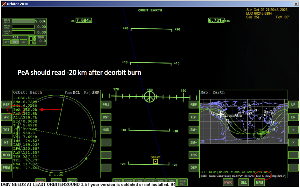
- 5. After the burn continue along your present orbit. The distance between you and the base is displayed at the bottom of Map MFD. First the distance will decrease and then increase as you pass the Cape. After you have passed it, the distance will reach a maximum of about 19.6 Mm (Million meters, or thousand kilometers) and then distance starts to decrease again. At that time, turn retrograde and at exactly 16.0 Mm from the Cape burn the main engines until the periapsis (PeA) is -20 km in Orbit MFD. This will set up an entry interface at 120 km positioned a distance of 5370 km from the base.
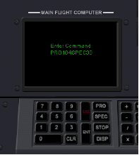
- 6. Now the Deltaglider IV has to be programmed. Go to the lower panel and press PRO on the computer keyboard then press 104. Then press SPEC and type in 30. This will set your angle of attack at 30° to the direction of motion for reentry. Press E to engage the autopilot, or click on the flight computer’s EXE button (the red one).
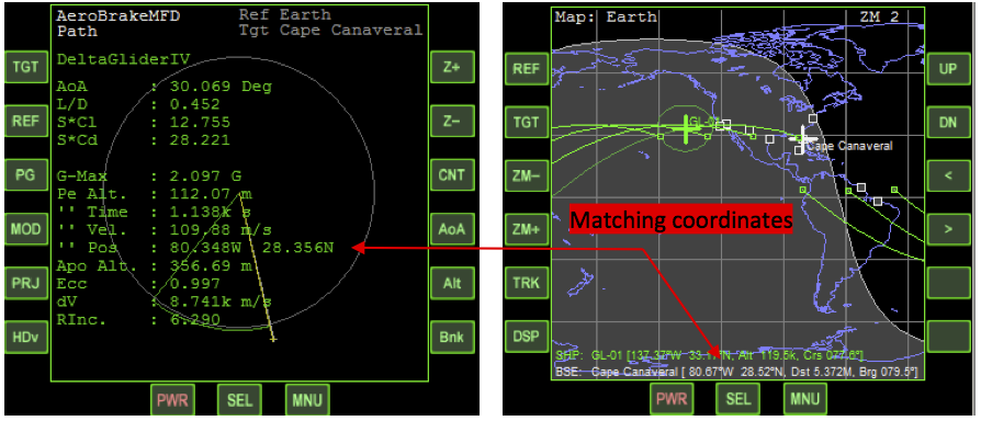
- 7. Bring up Aerobrake MFD to monitor your progress. Set the target to Cape Canaveral (Press TGT, then enter Cape Canaveral). The landing site coordinates should match those of your base, within a degree of accuracy.
- 8. Aerodynamics and gravity will now conspire to bring you over the Cape at an altitude between 20 and 30 km altitude and with a velocity of 2 km per second, rapidly decreasing. It is then possible to do a turn over the Atlantic and come in from the sea, perhaps with some help from the engines. Welcome home!
Diversion to Habana (advanced)
Here I have been impatient to get down to Earth. I thought I could use the Deltaglider’s advanced aerodynamic properties to swoop down to the Cape. Only I have not planned my reentry properly and will overshoot my intended landing spot. Habana is however conveniently in my path and I can easily relocate to there. Below is a list of events and related information to fly to Habana. Your times, altitude and speed for the events will vary slightly.
| t (s) | Alt (km) | v (km/s) | Event |
|---|---|---|---|
| 0 | 362.2 | 7.411 | Scenario start |
| 2 | 362.2 | 7.411 | Undock from ISS (CTRL-D) |
| 10 | 362.2 | 7.411 | Close nose door (top panel) |
| 20 | 362.2 | 7.411 | Target Cape Canaveral on Map MFD |
| 30 | 362.2 | 7.411 | Select Orbit MFD on left side |
| 509 | 360.4 | 7.411 | Turn retrograde (middle panel on left) |
| 4530 | 361.2 | 7.333 | At a distance of 19000 km from the Cape burn main engines for about 20 s to deorbit. The important thing is to watch the PeA value on Orbit MFD. When that gets to -20 km stop the burn.
Remember to set PeA to “distance from surface” by pressing the DST button. |
| 4540 | 361.2 | 7.294 | End of burn (approximately) |
| 4560 | 361.1 | 7.295 | Turn prograde |
| 5750 | 196.1 | 7.500 | Prepare for entry using reentry autopilot
Select lower panel (CTRL-down arrow) Press PRO on main flight computer keyboard Type “104” Press SPEC on main flight computer Type “20” and press enter Activate autopilot by pressing “E” |
| 5850 | Bank to +60° by pressing numpad 4 | ||
| 5950 | Select Aerobrake MFD in left and enter Cape Canaveral as the target | ||
| 6110 | 120.0 | 7.583 | At the entry interface you are about 8600 km from Cape Canaveral |
| 6736 | 86.87 | 7.100 | Cross the west coast of North America. As you get close to the Cape use bank angle to keep on target (numpad 4 & 6) |
| 7452 | 57.03 | 4.505 | As you pass Cape Canaveral, Habana will be in sight if you have the base markers activated in Orbiter’s planetarium mode |
| 7485 | 54.95 | 4.224 | Select Habana as your new target on Map MFD and Aerobrake MFD. |
| 7713 | 42.76 | 2.150 | You are over Habana. Speed and altitude will decrease fast. Prepare for landing. |
[The pictures that follow are taken in glass cockpit mode just for convenience of illustration.]
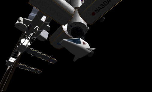
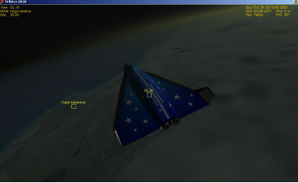
About to undock
Before deorbit burn
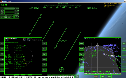
Close to reentry. Banking steeply to get the lift forces to pull south towards the Cape.
| Chapter 5: Dancing In The Dark | GPIS Contents | Chapter 7: Mars Awaits |

