File:ToddWessShuttleDiagram1.gif
Revision as of 20:18, 9 November 2008 by Yagni01 (talk | contribs) (The figure below shows dimensions and cutting pattern for parts L1, L2, R1, R2 and the base for C5, C6 & C7 to be cut from a piece of 48”x48” material. I used 1/8” plywood. When joining two pieces together, the joint was reinforced from below with �)

Size of this preview: 578 × 599 pixels. Other resolutions: 231 × 240 pixels | 1,951 × 2,023 pixels.
Original file (1,951 × 2,023 pixels, file size: 62 KB, MIME type: image/gif)
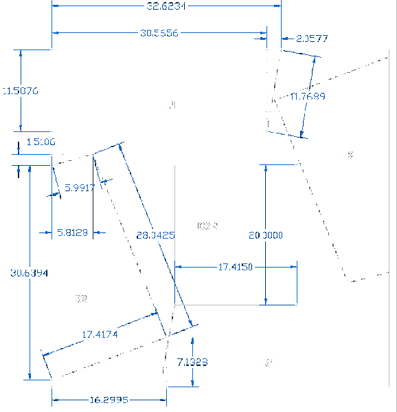
The figure below shows dimensions and cutting pattern for parts L1, L2, R1, R2 and the base for C5, C6 & C7 to be cut from a piece of 48”x48” material. I used 1/8” plywood. When joining two pieces together, the joint was reinforced from below with ½”x1 ½” wood. All units are in inches.
File history
Click on a date/time to view the file as it appeared at that time.
| Date/Time | Thumbnail | Dimensions | User | Comment | |
|---|---|---|---|---|---|
| current | 20:18, 9 November 2008 |  | 1,951 × 2,023 (62 KB) | Yagni01 (talk | contribs) | The figure below shows dimensions and cutting pattern for parts L1, L2, R1, R2 and the base for C5, C6 & C7 to be cut from a piece of 48”x48” material. I used 1/8” plywood. When joining two pieces together, the joint was reinforced from below with � |
You cannot overwrite this file.
File usage
The following page uses this file: